-53-
Introduction
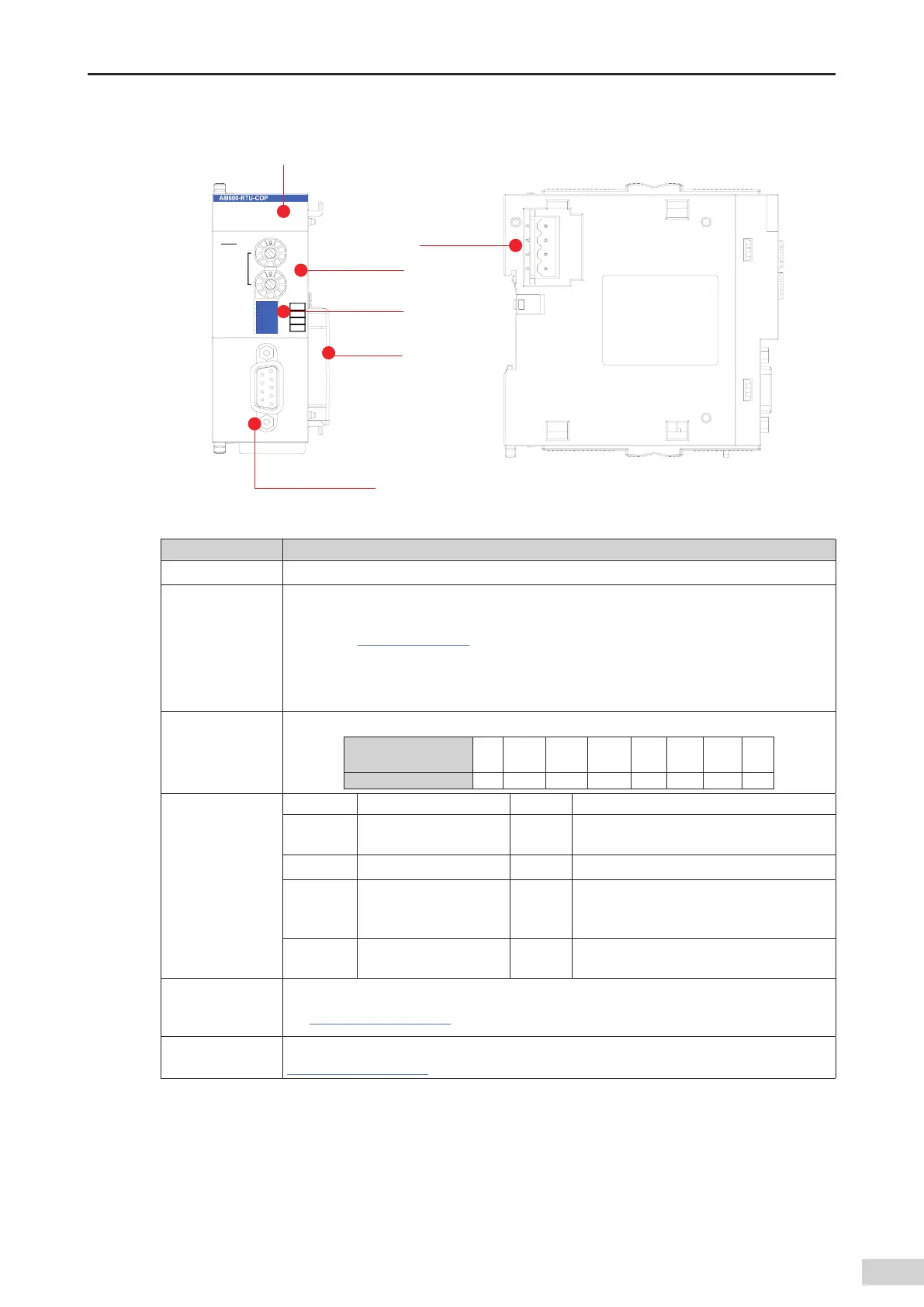
2) Module interface description
$"/&33
$"/36/
108&3
#'
4'
9
"%%3&44
9
#"6%
$"/0QFO
#3
#3
3
#3
7
7
(/%
(/%
$01
4JHOBMJOEJDBUPS
%#JOUFSGBDF
GFNBMFDPOOFDUPS
-PDBMFYQBOTJPO
CBDLFOE
JOUFSGBDF
$PEFTXJUDI
*OUFSOBM7
QPXFS
JOQVUUFSNJOBM
%*1TXJUDI
Figure 3-32 CANopen module interfaces
Interface Name Function
DB9 interface CANopen communication port
Address switch
(rotary switch)
This 16-bit rotary switch is used to set the station address.
Decimal slave station address = ADDR1 x 16 + ADDR0 (address range: 1 to 63). For details about
the use
,
see
"Chapter 5 Wiring"
.
Note: The maximum address that this switch can set is 153 (9 x 16 + 9 x 1). The CANopen
station number range is 1 to 127. Therefore
,
you need to avoid using station numbers greater
than 127.
Baud rate selection
switch (DIP switch)
The DIP switch is used to set the baud rate.
Value of DIP Switch 0 1 2 3 4 5 6 7
Baud Rate (bps) 1 M 800 K 500 K 250 K 125 K 50 K 20 K 10 K
Signal indicators
POWER Power indicator Green On when the power is switched on
CANRUN
CAN bus running
indicator
Green On when the module is running normally
CANERR CAN bus error indicator Red On when a CAN bus error occurs
SF
Slave station
conguration error
indicator
Red
On when a conguration error of the slave
station expansion module occurs
BF
Slave station expansion
bus error indicator
Red
Blinks when an error of the slave station
expansion module occurs
Local expansion
module back-end
interface
Connects to the backward module and does not support hot swap. For details about the use
,
see
"Chapter 4 Installation"
.
Internal 24 V power
input terminal
Connects to the power module and does not support hot swap. For details about the use
,
see
"Chapter 4 Installation"
.

 Loading...


