Chapter2TechnicalSpecificationsandElectricalInstallation
11
2.3 Electrical Wiring
The electrical wiring figures below are aiming at helping the users who initially use the
servo drive to be able to perform the operations described in the troubleshooting process.
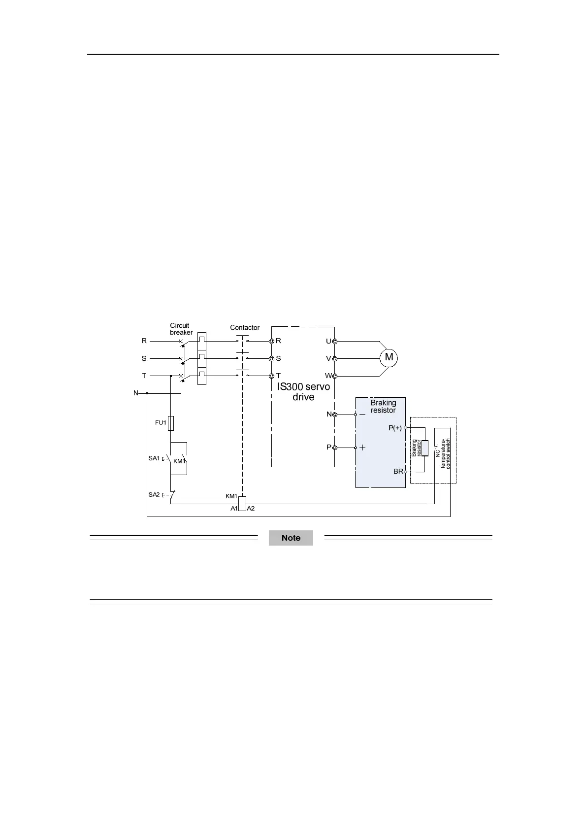
2.3.1 Wiring of the External Braking Unit
Two wiring methods are provided, differing in the wiring of braking resistor overheat
protection.
Wiring method 1: After the signal of the braking resistor overheat relay is sent, the power
supply of the IS300 is cut off.
Wiring method 2: The signal of the braking resistor overheat relay is used as input of the
IS300 external fault (Err15).
Figure 3-18 Basic wiring method 1
In this wiring method, the input voltage class of the contactor control coil is 220 VAC. The NC contact of
the thermal relay is connected to the power supply of the wire package driven by the main contactor.
When a fault occurs, the driving power supply of the contactor is cut off to disconnect the main contactor.

 Loading...

