89
En
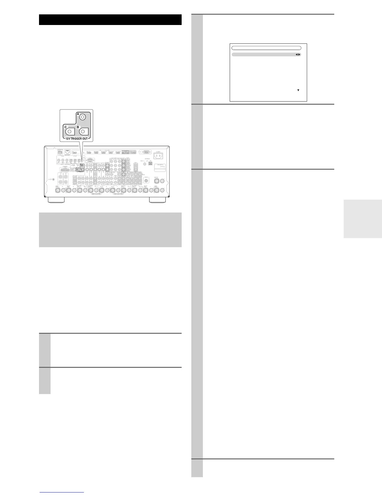
The 12V triggers A, B, and C can be used to turn on 12V
trigger-capable components automatically when they are
selected as the input source. The triggers can be set so that
they activate when a connected component is selected as
the input source for the main room, Zone 2, Zone 3, Zone
4, or any combination of rooms.
When triggered, the output from a 12V TRIGGER OUT
goes high (+12 volts and 150 milliamperes max. at TRIG-
GER OUT A; +12 volts and 25 milliamperes max. at
TRIGGER OUT B and C).
When several components are turned on simultaneously
by using triggers A, B, and C, depending on the type of
components, a large amount of current may be drawn
momentarily. To prevent this, you can delay trigger signals
A, B, and C individually. Another application for trigger
delay is eliminating the “thump” noise that’s sometimes
heard when a source component is turned on.
Delaying the trigger signal for your power amplifier so
that it’s the last component to be turned on will accom-
plish this.
Using the 12V Triggers
Hookup
• Use a miniplug cable to connect the AV receiver’s 12V
TRIGGER OUT A, B, or C jack to the 12 V trigger
input on a connected component.
1
Press Receiver followed by Setup.
The main menu appears onscreen.
If the main menu doesn’t appear, make sure the
appropriate external input is selected on your TV.
2
Use q/w to select “Miscellaneous” and then press
Enter.
The “Miscellaneous” menu appears.
3
Use q/w to select “12V Trigger A, B, or C Setup”
and then press Enter.
The “12V Trigger A/B/C Setup” screen appears.
4
Use q/w to select “Delay,” and use e/r to select
trigger signals.
` 0sec (Trigger A: default),
1sec (Trigger B: default),
2sec (Trigger C: default),
or 3sec.
When “0sec” is selected, the trigger signal is output
as soon as the input source is changed.
5
Use q/w to select an input source, and use e/r to
select an option.
` Off:
No trigger signal is output.
A 12-volt trigger signal is output when the connected
component is selected as the source for:
` Main (Trigger A: default):
Main room.
` Zone 2 (Trigger C: default):
Zone 2.
` Main/Zone 2:
Main room or Zone 2.
` Zone 3:
Zone 3.
` Main/Zone 3:
Main room or Zone 3.
` Zone 2/Zone 3:
Zone 2 or Zone 3.
` Main/Zone 2/Zone 3:
Main room, Zone 2, or Zone 3.
` Zone 4:
Zone 4.
` Main/Zone 4:
Main room or Zone 4.
` Zone 2/Zone 4:
Zone 2 or Zone 4.
` Main/Zone 2/Zone 4:
Main room, Zone 2, or Zone 4.
` Zone 3/Zone 4:
Zone 3 or Zone 4.
` Main/Zone 3/Zone 4:
Main room, Zone 3, or Zone 4.
` Zone 2/Zone 3/Zone 4:
Zone 2, Zone 3 or Zone 4.
` Main/Zone 2/Zone 3/Zone 4 (Trigger B:
default):
Main room, Zone 2, Zone 3, or Zone 4.
6
When you’ve finished, press Setup.
The setup menu closes.
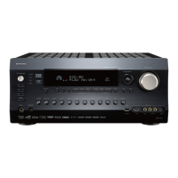
6–3. 12V Trigger A Setup
Delay
BD/DVD
VCR/DVR
CBL/SAT
GAME
PC
AUX
0sec
Main
Main
Main
Main
Main
Main