Hardware Setup 19
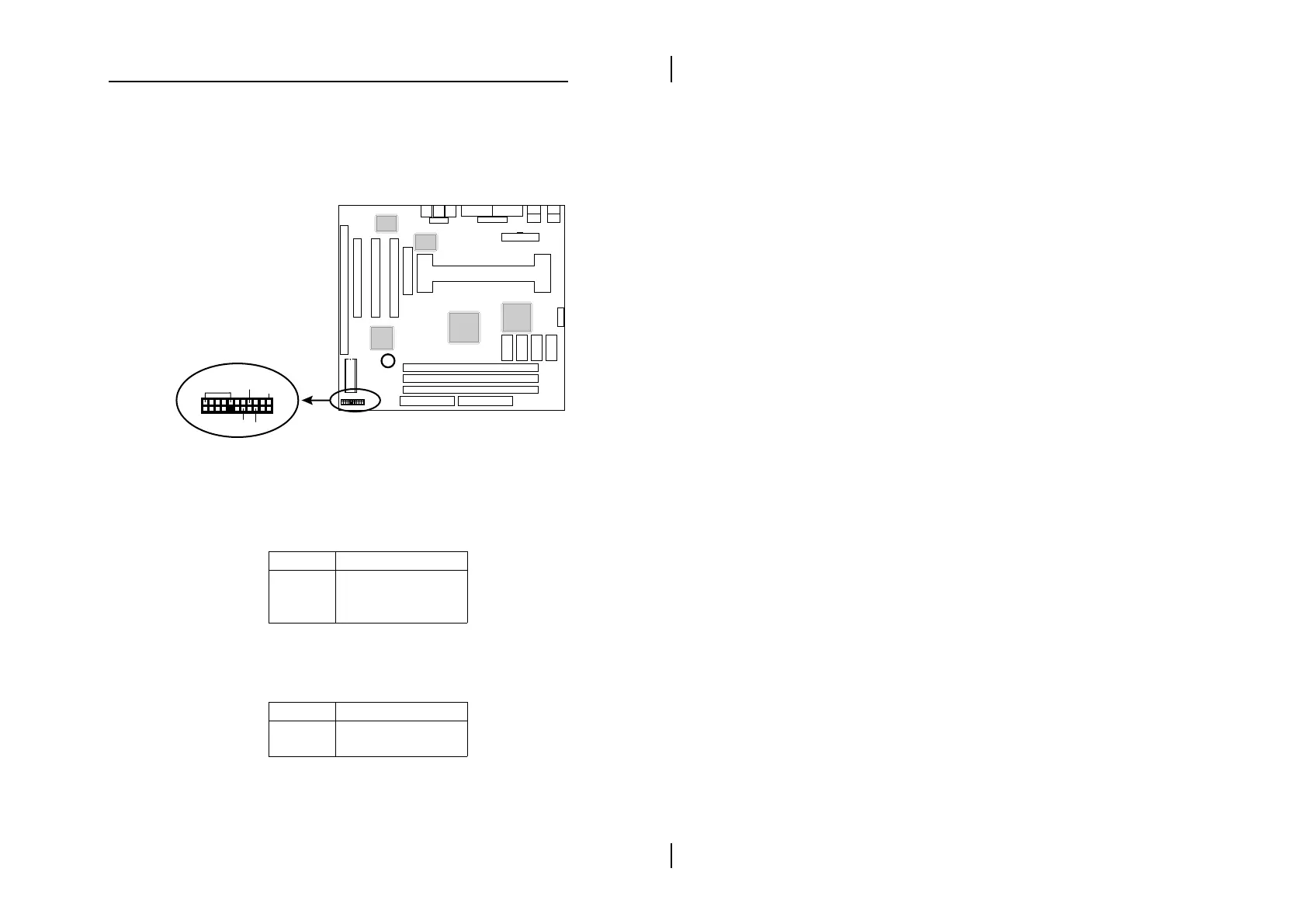
Case Connectors: J11
This connector contains: Speaker, Power LED, Keylock,
Suspend LED, HDD LED, Reset Switch, and Power
Button. Refer to the following drawing for the location on
the mainboard.
+
Chipset
Sound Pro
VGA
Chipset
I/O Chip
SPK
RST
PWRBT
KY-LOCK
22
21
1
2
SP-LED
J11
HD-LED
pin1, 3, 5, 7 – Speaker
pin2, 4, 6 – Power LED
pin8, 10 – Keylock
pin13, 14 – Suspend LED
pin15, 16 – HDD LED
pin17, 18 – Reset Switch
pin21, 22 – Power Button
(refer to ATX Functions & Connectors section)
J11 (2, 4, 6) (Power LED) – Power LED
Connector
Keylock connector enables and disables the keyboard
key-in function on the case.
Pin Description
2 LED Output
4 N.C.
6 Ground
J11 (8, 10) (KEYLOCK) – KeyLock Switch
Connector
Setting Description
Open Nomral Mode
Close Lock K/B