Quad-Core Intel® Xeon® Processor 5400 Series TMDG 25
Thermal/Mechanical Reference Design
above, the case-to-ambient resistance represents the slope of the line and the
processor local ambient temperature represents the y-axis intercept. Hence the
T
CASE_MAX
value of a specific solution can be calculated at TDP. Once this point is
determined, the line can be extended to Power (P) = 0W representing the Thermal
Profile of the specific solution. If that line stays at or below the Thermal Profile
specification, then that particular solution is deemed as a compliant solution.
2.2.6 T
CONTROL
Definition
T
CONTROL
can be described as a trigger point for fan speed control implementation. The
processor T
CONTROL
value provided by the Digital Thermal Sensor is relative and no
longer absolute. The T
CONTROL
value is now defined as a relative value to the TCC
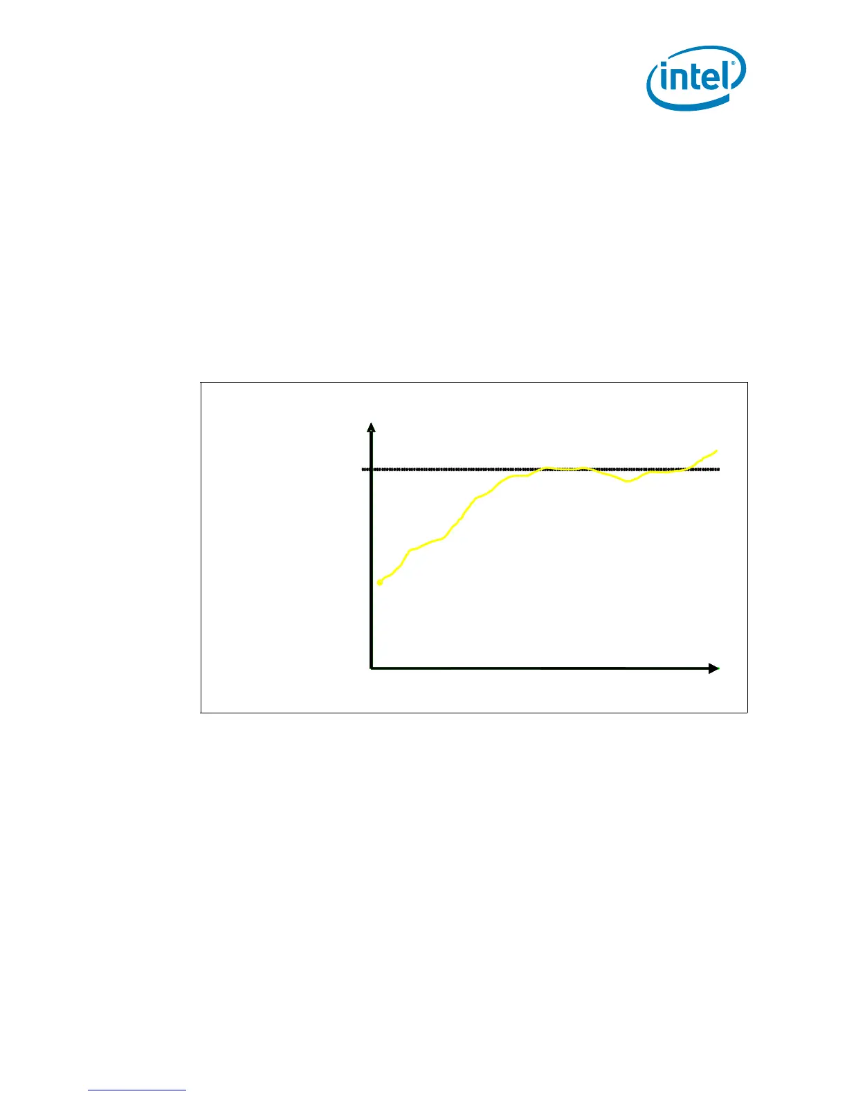
activation set point (i.e. PECI Count = 0), as indicated by PROCHOT#. Figure 2-8
depicts the interaction between the T
CONTROL
value and Digital Thermal Sensor value.
The value for T
CONTROL
is calibrated in manufacturing and configured for each processor
individually. For the Quad-Core Intel® Xeon® Processor 5400 Series, the T
CONTROL
value is obtained by reading the processor model specific register
(IA32_TEMPERATURE_TARGET MSR).
Note: There is no T
CONTROL_BASE
value to sum as previously required on legacy processors.
The fan speed control device only needs to read the T
OFFSET MSR
and compare this to
the DTS value from the PECI interface. The equation for calculating T
CONTROL
is:
Equation 2-2.T
CONTROL
= -T
OFFSET
Where:
T
OFFSET
= A DTS-based value programmed into each processor during
manufacturing that can be obtained by reading the
IA32_TEMPERATURE_TARGET MSR. This is a static and a unique value.
Refer to the RS - Wolfdale Processor Family BIOS Writer’s Guide (BWG)
for further details.
Figure 2-8. T
CONTROL
Value and Digital Thermal Sensor Value Interaction
-30
-20
-10
0
-40
Time
Digital Thermal Sensor Temperature
Tcontrol = -5
Temperature
-30
-20
-10
0
-40
-30
-20
-10
0
-40
Time
Digital Thermal Sensor Temperature
Tcontrol = -5
Temperature