EasyManuals Logo

Intel 5400 Series User Manual

Intel 5400 Series
100 pages
To Next Page IconTo Next Page
To Previous Page IconTo Previous Page
Page #39 background imageLoading...
Page #39 background image
Quad-Core Intel® Xeon® Processor 5400 Series TMDG 39
Thermal/Mechanical Reference Design
2.5.4 Assembly Overview of the Intel Reference Thermal
Mechanical Design
The reference design heatsinks that meet the Quad-Core Intel® Xeon® Processor 5400
Series thermal performance targets are called the Common Enabling Kit (CEK)
heatsinks, and are available in 1U, 2U, & 2U+ form factors. Each CEK consists of the
following components:
Heatsink (with captive standoff and screws)
Thermal Interface Material (TIM)
•CEK Spring
2.5.4.1 Geometric Envelope
The baseboard keepout zones on the primary and secondary sides and height
restrictions under the enabling component region are shown in detail in Appendix B.
The overall volumetric keep in zone encapsulates the processor, socket, and the entire
thermal/mechanical enabling solution.
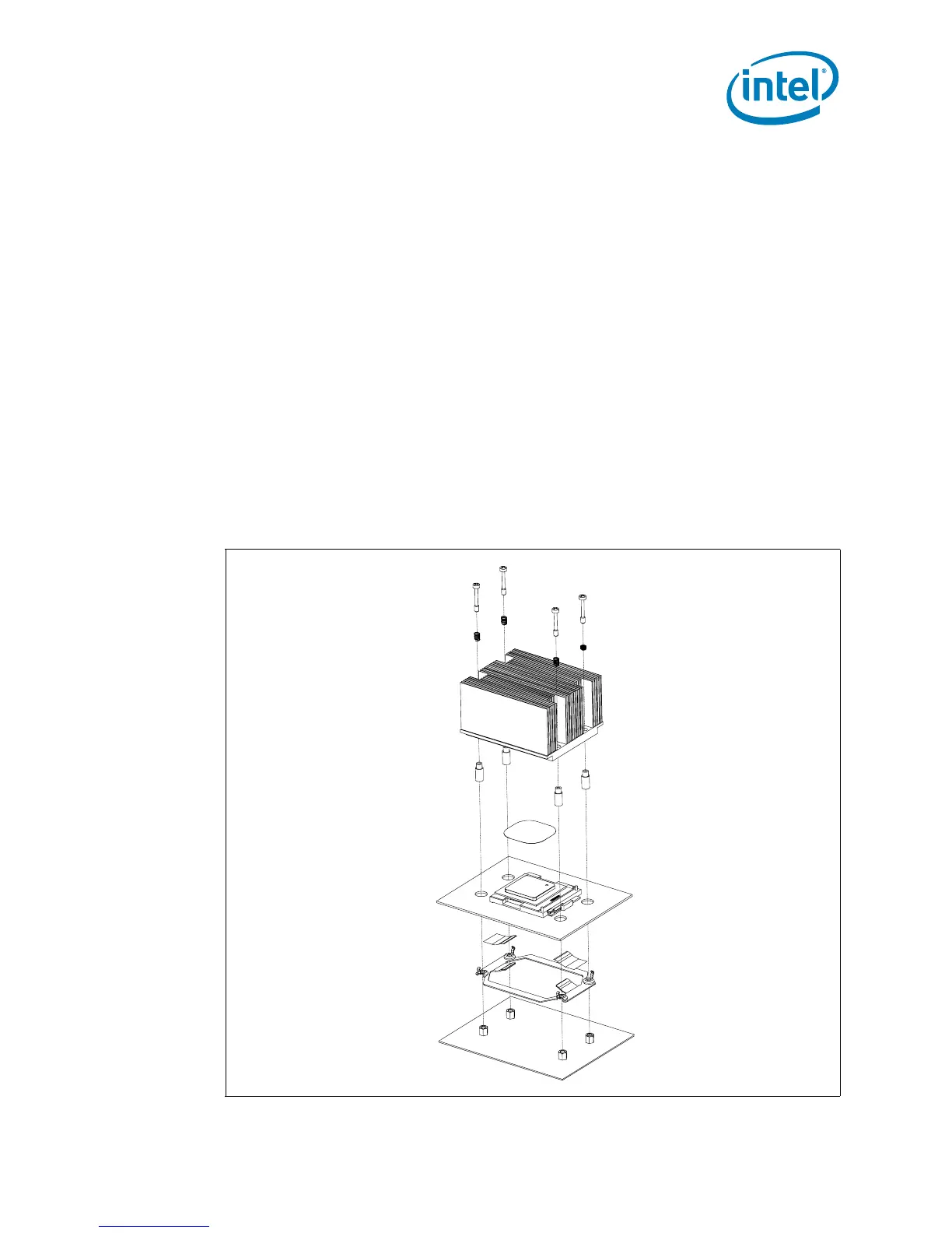
2.5.4.2 Assembly Drawing
Figure 2-16. Exploded View of CEK Thermal Solution Components

Table of Contents

Questions and Answers:

Question and Answer IconNeed help?

Do you have a question about the Intel 5400 Series and is the answer not in the manual?

Intel 5400 Series Specifications

General IconGeneral
Processor TypeXeon
SocketLGA 771
Lithography65 nm
Chipset CategoryServer
Memory Channels4
ECC SupportYes
Integrated GraphicsNo
Process Technology65 nm
Virtualization TechnologyYes
Release Date2007
ArchitectureCore
Supported CPUDual-Core and Quad-Core Xeon
FSB1333 MHz/1600 MHz
Memory TypeFB-DIMM
Model5400 Series
Number of Threads4
L2 Cache2 x 6 MB
Memory SupportDDR2 FB-DIMM
Instruction Set64-bit
Number of CoresQuad-Core

Related product manuals