Quad-Core Intel® Xeon® Processor 5400 Series TMDG 51
Thermal/Mechanical Reference Design
2.5.8.2 Systems Considerations Associated with the Active CEK
This heatsink was designed to help pedestal chassis users to meet the processor
thermal requirements without the use of chassis ducting. It may be necessary to
implement some form of chassis air guide or air duct to meet the T
LA
temperature of
40 °C depending on the pedestal chassis layout. Also, while the active heatsink solution
is designed to mechanically fit into a 2U chassis, it may require additional space at the
top of the heatsink to allow sufficient airflow into the heatsink fan. Therefore, additional
design criteria may need to be considered if this heatsink is used in a 2U rack mount
chassis, or in a chassis that has drive bay obstructions above the inlet to the fan
heatsink.
Thermal Profile A should be used to help determine the thermal performance of the
platform. The primary recommended control method for this solution is using pulse
width modulation control. This control method requires the motherboard provide the
correct PWM duty cycle to the active fan heatsink solution to properly follow the
thermal profile. If no PWM signal is detected the active heatsink solution will default
back to a thermistor controlled mode and the fan will automatically adjust fan RPM to
meet the thermal profile.
It is critical to supply a constant +12 V to the fan header so that the active CEK
heatsink solution can operate properly. If a system board has a jumper setting to select
either a constant +12 V power to the fan header or a variable voltage, it is strongly
recommended that the jumper be set by default to the constant +12 V setting.
It is recommended that the ambient air temperature outside of the chassis be kept at
or below 35 °C. The air passing directly over the processor heatsink should not be
preheated by other system components. Meeting the processor’s temperature
specification is the responsibility of the system integrator.
2.5.8.3 Boxed Processor Contents
A direct chassis attach method must be used to avoid problems related to shock and
vibration, due to the weight of the heatsink required to cool the processor. The board
must not bend beyond specification in order to avoid damage. The boxed processor
contains the components necessary to solve both issues. The boxed processor will
include the following items:
• Quad-Core Intel® Xeon® Processor 5400 Series
• Unattached heatsink solution
• 4 screws, 4 springs, and 4 heatsink standoffs (all captive to the heatsink)
• Thermal Interface Material (pre-applied on heatsink)
• Installation Manual
•Intel Inside
®
logo
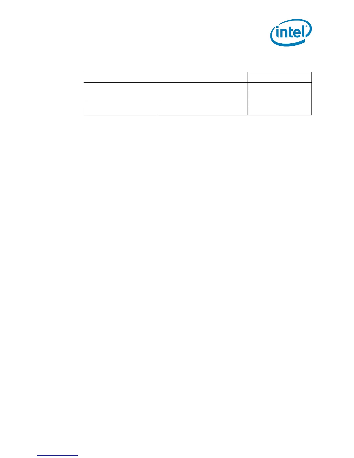
Table 2-10. Fan Cable Connector Pin Out (Active CEK)
Pin Number Signal Color
1 Ground (Constant) Black
2 Power (+12V) Yellow
3 Signal: 2 pulses per revolution Green
4 Control 21KHz - 28KHz Blue