8XC251SA, SB, SP, SQ USER’S MANUAL
8-4
For normal timer operation (GATE0 = 0), setting TR0 allows TL0 to be incremented by the se-
lected input. Setting GATE0 and TR0 allows external pin INT0# to control timer operation. This
setup can be used to make pulse width measurements. See section 8.5.2, “Pulse Width Measure-
ments.”
Timer 0 overflow (count rolls over from all 1s to all 0s) sets the TF0 flag generating an interrupt
request.
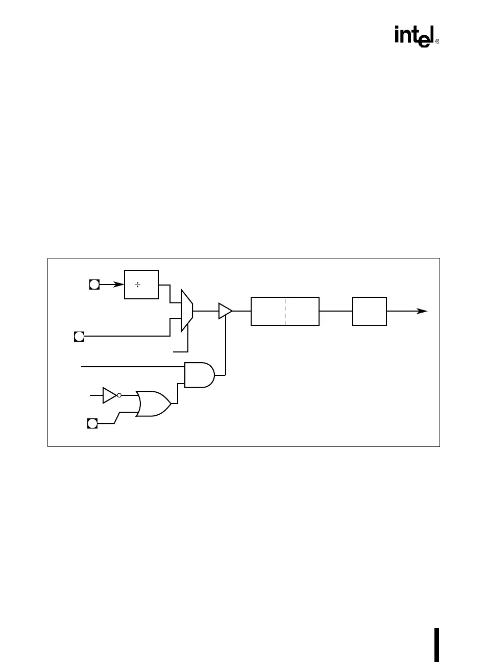
8.3.1 Mode 0 (13-bit Timer)
Mode 0 configures timer 0 as a 13-bit timer which is set up as an 8-bit timer (TH0 register) with
a modulo 32 prescalar implemented with the lower five bits of the TL0 register (Figure 8-2). The
upper three bits of the TL0 register are indeterminate and should be ignored. Prescalar overflow
increments the TH0 register.
Figure 8-2. Timer 0/1 in Mode 0 and Mode 1
8.3.2 Mode 1 (16-bit Timer)
Mode 1 configures timer 0 as a 16-bit timer with TH0 and TL0 connected in cascade (Figure 8-2).
The selected input increments TL0.
A4110-02
GATE
x
INT
x
#
TR
x
TL
x
(8 Bits)
TH
x
(8 Bits)
TF
x
Interrupt
Request
12
T
x
Overflow
Mode 0: 13-bit Timer/Counter
Mode 1: 16-bit Timer/Counter
x
= 0 or 1
XTAL1
C/T
x
#
0
1