8XC251SA, SB, SP, SQ USER’S MANUAL
2-6
2.2.2 Clock and Reset Unit
The timing source for the 8XC251Sx can be an external oscillator or an internal oscillator with
an external crystal/resonator (see Chapter 11, “Minimum Hardware Setup”). The basic unit of
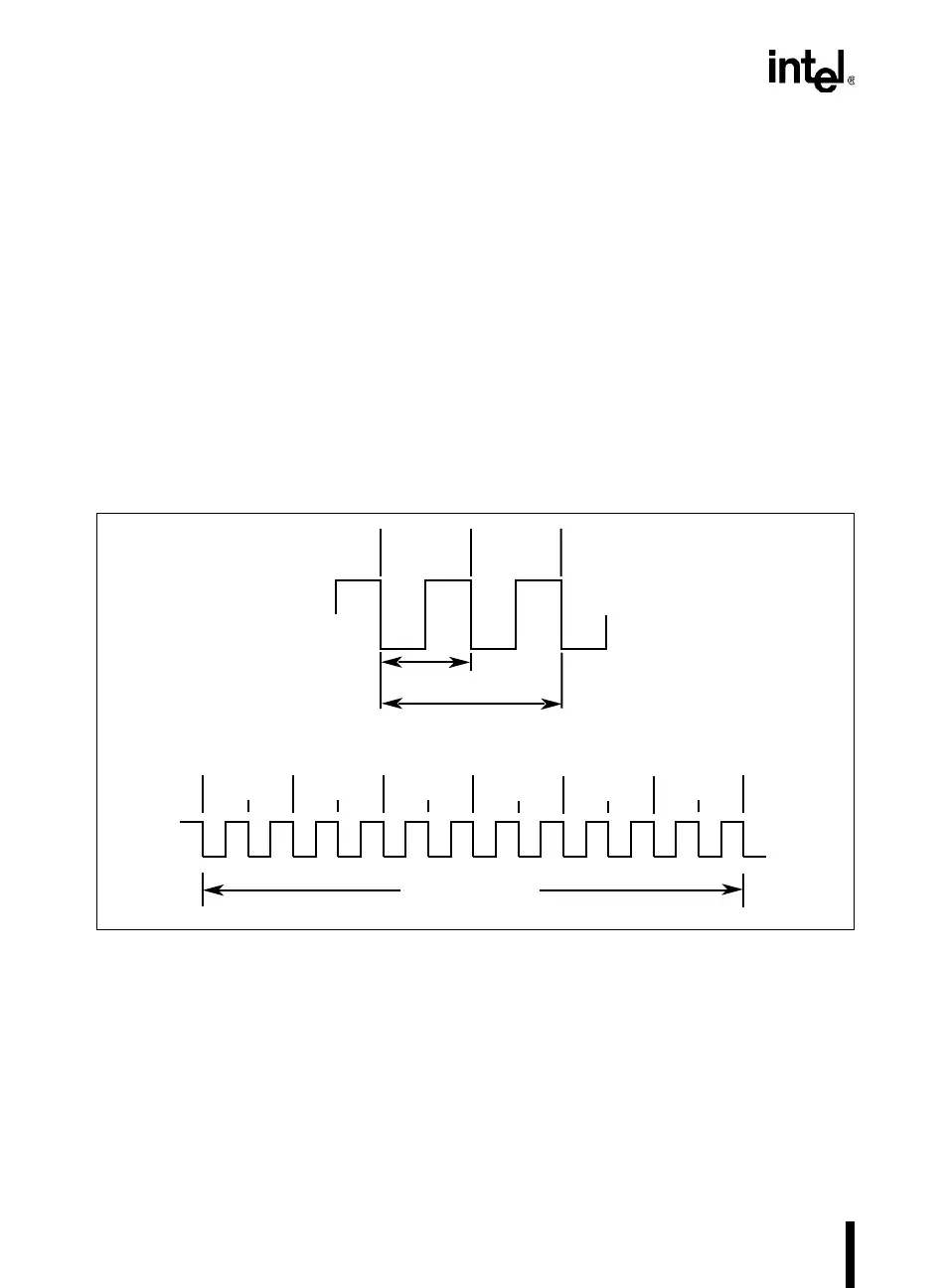
time in MCS 251 microcontrollers is the state time (or state), which is two oscillator periods (see
Figure 2-3). The state time is divided into phase 1 and phase 2.
The 8XC251Sx peripherals operate on a peripheral cycle, which is six state times. (This periph-
eral cycle is particular to the 8XC251Sx and not a characteristic of the MCS 251 architecture.) A
one-clock interval in a peripheral cycle is denoted by its state and phase. For example, the PCA
timer is incremented once each peripheral cycle in phase 2 of state 5 (denoted as S5P2).
The reset unit places the 8XC251Sx into a known state. A chip reset is initiated by asserting the
RST pin or allowing the watchdog timer to time out (see Chapter 11, “Minimum Hardware Set-
up”).
Figure 2-3. Clocking Definitions
T
OSC
State 2
P1
P2
State 1
P1
P2
State 3
P1
P2
State 4
P1
P2
State 5
P1
P2
State 6
P1
P2
Peripheral Cycle
2 T
OSC
= State Time
XTAL1
XTAL1
P1
P2
A2604-02
Phase 1 Phase 2