9-11
PROGRAMMABLE COUNTER ARRAY
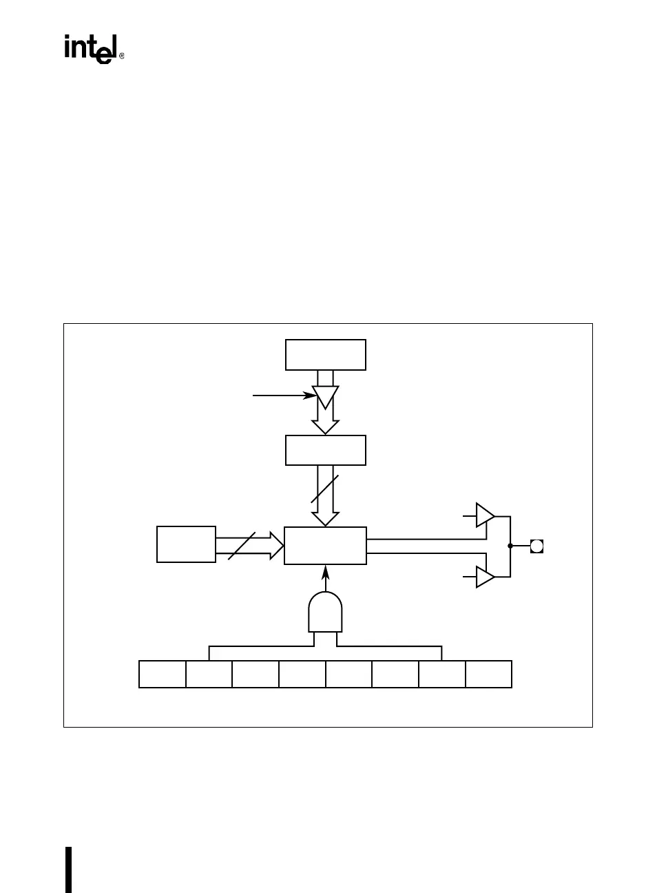
9.3.6 Pulse Width Modulation Mode
The five PCA comparator/capture modules can be independently programmed to function as
pulse width modulators (Figure 9-5). The modulated output, which has a pulse width resolution
of eight bits, is available at the CEXx pin. The PWM output can be used to convert digital data to
an analog signal with simple external circuitry.
In this mode the value in the low byte of the PCA timer/counter (CL) is continuously compared
with the value in the low byte of the compare/capture register (CCAPxL). When CL < CCAPxL,
the output waveform (Figure 9-6) is low. When a match occurs (CL = CCAPxL), the output wave-
form goes high and remains high until CL rolls over from FFH to 00H, ending the period. At roll-
over the output returns to a low, the value in CCAPxH is loaded into CCAPxL, and a new period
begins.
Figure 9-5. PCA 8-bit PWM Mode
A4166-01
CCAP
x
H
CEX
x
X ECOM
x
0 0 0 PWM
x
00
07
CCAPM
x
Mode Register
X = Don't Care
x
= 0, 1, 2, 3, 4.
8-Bit
Comparator
CL rollover from FFH to 00H loads
CCAP
x
H contents into CCAP
x
L
"0"
"1"
CL ≥ CCAP
x
L
CL < CCAP
x
L
CCAP
x
L
CL
(8 Bits)
8
8
Enable