8XC251SA, SB, SP, SQ USER’S MANUAL
8-8
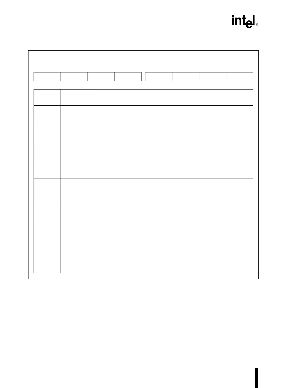
Figure 8-6. TCON: Timer/Counter Control Register
When timer 0 is in mode 3, it uses timer 1’s overflow flag (TF1) and run control bit (TR1). For
this situation, use timer 1 only for applications that do not require an interrupt (such as a baud rate
generator for the serial interface port) and switch timer 1 in and out of mode 3 to turn it off and on.
TCON
Address: S:88H
Reset State: 0000 0000B
7 0
TF1 TR1 TF0 TR0 IE1 IT1 IE0 IT0
Bit
Number
Bit
Mnemonic
Function
7 TF1 Timer 1 Overflow Flag:
Set by hardware when the timer 1 register overflows. Cleared by
hardware when the processor vectors to the interrupt routine.
6 TR1 Timer 1 Run Control Bit:
Set/cleared by software to turn timer 1 on/off.
5 TF0 Timer 0 Overflow Flag:
Set by hardware when the timer 0 register overflows. Cleared by
hardware when the processor vectors to the interrupt routine.
4 TR0 Timer 0 Run Control Bit:
Set/cleared by software to turn timer 0 on/off.
3 IE1 Interrupt 1 Flag:
Set by hardware when an external interrupt is detected on the INT1# pin.
Edge- or level- triggered (see IT1). Cleared when interrupt is processed
if edge-triggered.
2 IT1 Interrupt 1 Type Control Bit:
Set this bit to select edge-triggered (high-to-low) for external interrupt 1.
Clear this bit to select level-triggered (active low).
1 IE0 Interrupt 1 Flag:
Set by hardware when an external interrupt is detected on the INT0# pin.
Edge- or level- triggered (see IT0). Cleared when interrupt is processed
if edge-triggered.
0 IT0 Interrupt 0 Type Control Bit:
Set this bit to select edge-triggered (high-to-low) for external interrupt 0.
Clear this bit to select level-triggered (active low).