9-15
PROGRAMMABLE COUNTER ARRAY
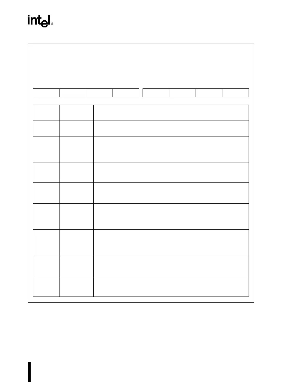
Figure 9-9. CCAPM
x
: PCA Compare/Capture Module Mode Registers
CCAPM
x
(
x
= 0–4)
Address: CCAPM0 S:DAH
CCAPM1 S:DBH
CCAPM2 S:DCH
CCAPM3 S:DDH
CCAPM4 S:DEH
Reset State: X000 0000B
7 0
— ECOM
x
CAPP
x
CAPN
x
MAT
x
TOG
x
PWM
x
ECCF
x
Bit
Number
Bit
Mnemonic
Function
7 — Reserved:
The value read from this bit is indeterminate. Write a zero to this bit.
6 ECOM
x
Compare Modes:
ECOM
x
= 1 enables the module comparator function. The comparator is
used to implement the software timer, high-speed output, pulse width
modulation, and watchdog timer modes.
5CAPP
x
Capture Mode (Positive):
CAPP
x
= 1 enables the capture function with capture triggered by a
positive edge on pin CEX
x
.
4CAPN
x
Capture Mode (Negative):
CAPN
x
= 1 enables the capture function with capture triggered by a
negative edge on pin CEX
x
.
3MAT
x
Match:
Set ECOM
x
and MAT
x
to implement the software timer mode. When
MAT
x
= 1, a match of the PCA timer/counter with the compare/capture
register sets the CCF
x
bit in the CCON register, flagging an interrupt.
2TOG
x
Toggle:
Set ECOM
x,
MAT
x
, and TOG
x
to implement the high-speed output
mode. When TOG
x
= 1, a match of the PCA timer/counter with the
compare/capture register toggles the CEX
x
pin.
1PWM
x
Pulse Width Modulation Mode:
PWM
x
= 1 configures the module for operation as an 8-bit pulse width
modulator with output waveform on the CEX
x
pin.
0 ECCF
x
Enable CCF
x
Interrupt:
Enables compare/capture flag CCF
x
in the CCON register to generate
an interrupt request.