3-3
ADDRESS SPACES
The register file (registers R0–R7) comprises four switchable register banks, each having eight
registers. The 32 bytes required for the four banks occupy locations 00H–1FH in the on-chip data
memory.
Figure 3-3 shows how the address spaces in the MCS 51 architecture map into the address spaces
in the MCS 251 architecture; details are listed in Table 3-1.
The 64-Kbyte code memory for MCS 51 microcontrollers maps into region FF: of the memory
space for MCS 251 microcontrollers. Assemblers for MCS 251 microcontrollers assemble code
for MCS 51 microcontrollers into region FF:, and data accesses to code memory are directed to
this region. The assembler also maps the interrupt vectors to region FF:. This mapping is trans-
parent to the user; code executes just as before, without modification.
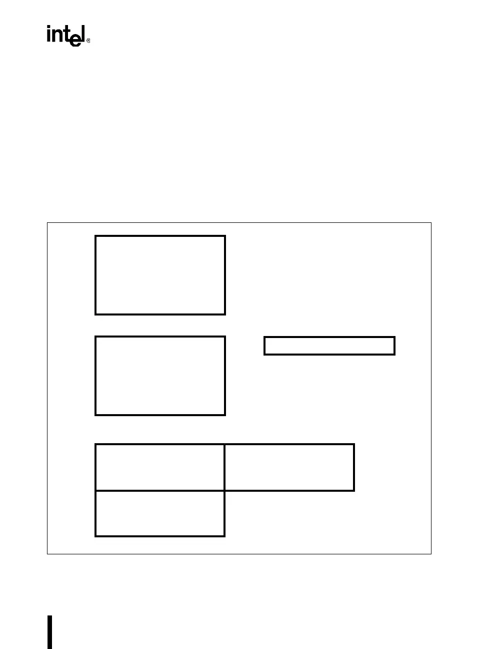
Figure 3-2. Address Spaces for the MCS
®
51 Architecture
External Data
(MOVX)
FFFFH
0000H
A4139-01
00H
FFH
80H
7FH
Code
(MOVC)
Internal Data
(direct, indirect)
Register File
SFRs
(direct)
Internal Data
(indirect)
0000H
FFFFH
80H
FFH
R7R0