Design and Environmental Specifications Intel® Server Boards S5520HC, S5500HCV, and S5520HCT TPS
Revision 1.8
Intel order number E39529-013
132
9.4.3 Remote Sense
The power supply should have remote sense return (ReturnS) to regulate out ground drops for
all output voltages: +3.3 V, +5 V, +12 V1, +12 V2, +12 V3, +12 V4, -12 V, and 5 VSB. The
power supply should use remote sense to regulate out drops in the system for the +3.3 V, +5 V,
and +12 V1 outputs.
The +12 V1, +12 V2, +12 V3, +12 V4, –12 V, and 5V SB outputs only use remote sense
referenced to the ReturnS signal. The remote sense input impedance to the power supply must
be greater than 200 Ω on 3.3 VS and 5 VS. This is the value of the resistor connecting the
remote sense to the output voltage internal to the power supply.
Remote sense must be able to regulate out a minimum of 200 mV drop. The remote sense
return (ReturnS) must be able to regulate out a minimum of 20 0mV drop in the power ground
return. The current in any remote sense line should be less than 5 mA to prevent voltage
sensing errors.
The power supply must operate within specification over the full range of voltage drops from the
power supply’s output connector to the remote sense points.
9.4.4 Voltage Regulation
The power supply output voltages must stay within the following voltage limits when operating at
steady state and dynamic loading conditions. These limits include the peak-peak ripple/noise.
All outputs are measured with reference to the return remote sense signal (ReturnS). The +12
V3, +12 V4, –12 V and 5 VSB outputs are measured at the power supply connectors referenced
to ReturnS. The +3.3 V, +5 V, +12 V1, and +12 V2 are measured at its remote sense signal
located at the signal connector.
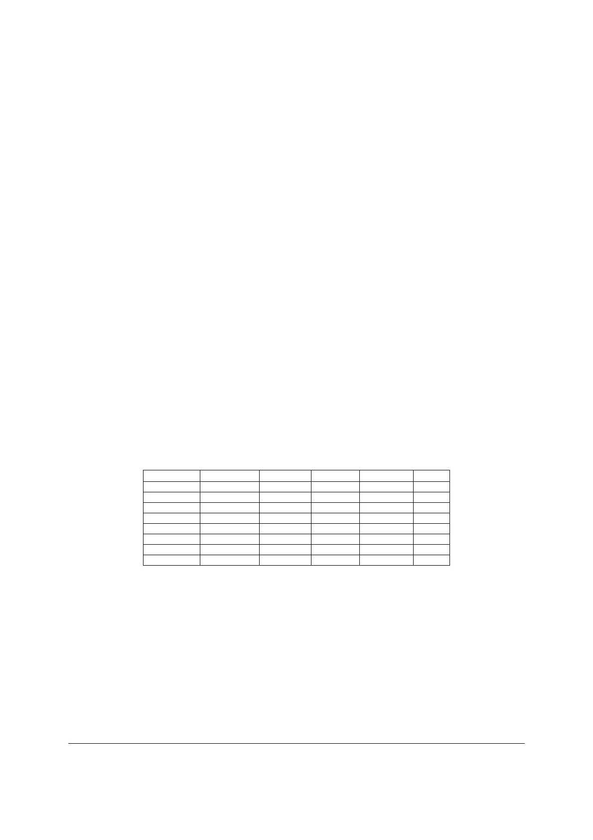
Table 75. Voltage Regulation Limits
Parameter Tolerance
Minimum
Nominal
Maximum
Units
+3.3 V - 5%/+5% +3.14V +3.30V +3.46V Vrms
+5 V - 5%/+5% +4.75V +5.00V +5.25V Vrms
+12 V 1 - 5%/+5% +11.40V +12.00V +12.60V Vrms
+12 V 2 - 5%/+5% +11.40V +12.00V +12.60V Vrms
+12 V 3 - 5%/+5% +11.40V +12.00V +12.60V Vrms
+12 V 4 - 5%/+5% +11.40V +12.00V +12.60V Vrms
- 12 V - 5%/+9% - 11.40V -12.00V -13.08V Vrms
+5 VSB - 5%/+5% +4.75V +5.00V +5.25V Vrms
9.4.5 Dynamic Loading
The output voltages remain within limits for the step loading and capacitive loading specified in
the following table. You should test the load transient repetition rate between 50 Hz and 5 kHz
at duty cycles ranging from 10% to 90%. The load transient repetition rate is only a test
specification. The Δ step load may occur anywhere within the minimum load to the maximum
load range.