EasyManua.ls Logo

Intel BB5520UR User Manual

Intel BB5520UR
190 pages
To Next Page IconTo Next Page
To Previous Page IconTo Previous Page
Page #21 background imageLoading...
Page #21 background image
Intel® Server Boards S5520HC, S5500HCV, and S5520HCT TPS Overview
Revision 1.8
Intel order number E39529-013
7
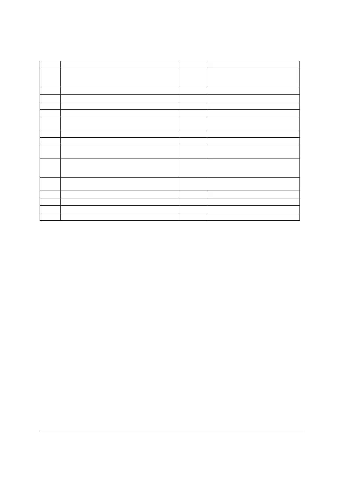
Callout Description Callout Description
Mechanically)
S5500HCV: Slot 6, PCI Express* Gen2 x4 (x16
Mechanically)
I Battery EE HSBP_B
J Back Panel I/O Ports FF SATA Port 2
K Diagnostic and Identify LED’s GG HSBP_A
L System Fan 5 Header (4-pin) HH SATA Port 3
M
Power Connector for Processor 1 and Memory
attached to Processor 1
II SATA Software RAID 5 Key Header
N Processor 1 Fan Header (4-pin) JJ Chassis Intrusion Header
O DIMM Sockets of Memory Channel A, B, and C KK SATA Port 4
P
Power Connector for Processor 2 and Memory
attached to Processor 2
LL SATA Port 5
Q Auxiliary Power Signal Connector MM
HDD Activity LED Header (Connect to
Add-in Card HDD Activity LED
Header)
R Processor 2 Fan Header (4-pin) NN
USB Connector (9-pin, for front panel
USB ports)
S DIMM Sockets of Memory Channel D, E, and F OO USB Connector (9-pin)
T SAS Module Slot PP Front Control Panel header
U System Fan 3 Header (6-pin) QQ DH-10 Serial B header
V System Fan 4 Header (6-pin)
Figure 3. Major Board Components

Table of Contents

Question and Answer IconNeed help?

Do you have a question about the Intel BB5520UR and is the answer not in the manual?

Intel BB5520UR Specifications

General IconGeneral
BrandIntel
ModelBB5520UR
CategoryServer Board
LanguageEnglish

Summary

Introduction to Intel Server Boards

Server Board Use Disclaimer

Provides important information regarding the use and limitations of Intel Server Boards.

Overview of Intel Server Boards S5520HC, S5500HCV, S5520HCT

Intel® Server Boards Feature Set

Details the key features and specifications of the server boards.

Server Board Connector and Component Layout

Identifies connectors and major components on the server board.

Server Board Mechanical Drawings

Illustrates the physical layout and dimensions of the server boards.

Server Board Rear I/O Layout

Shows the arrangement of rear input/output ports on the server board.

Functional Architecture of Intel Server Boards

Intel® 5520 and 5500 I/O Hub (IOH)

Describes the I/O Hub component and its platform functions.

Processor Support and Configuration

Details processor compatibility, population rules, and configuration options.

Memory Subsystem

Covers memory configuration, supported memory, and error handling.

ICH10R Component Details

Explains the ICH10R's I/O support, including SATA and RAID.

PCI Subsystem Overview

Details PCI and PCI Express bus segments and slot configurations.

SAS Entry RAID Module Support

Describes the optional SAS RAID module and its support.

Baseboard Management Controller (BMC)

Covers BMC features, embedded LAN channels, and management capabilities.

System Ports and Controllers

Details serial ports, video, NIC, USB, and other onboard controllers.

Trusted Platform Module (TPM) and TXT

Explains TPM security features and Intel® Trusted Execution Technology.

ACPI Support

Describes ACPI states and wake-up sources for system power management.

Intel® Virtualization Technology

Details Intel® Virtualization Technology and VT-d features.

Platform Management Features

IPMI and Non-IPMI Features

Lists supported IPMI 2.0 and non-IPMI features for server management.

Advanced Management Features

Covers KVM, Media Redirection, WS-MAN, Embedded Web Server, and LDAP.

Platform Control and Fan Speed Management

Explains system performance control, thermal throttling, and fan speed.

Intel® Intelligent Power Node Manager

Details the power management solution for monitoring and adjusting system variables.

BIOS Setup Utility

BIOS Setup Utility Overview

Introduces the BIOS setup utility, screens, and navigation.

Main Screen Configuration

Details the primary BIOS setup screen and its fields.

Advanced Screen Configurations

Provides access to detailed system configuration options.

Processor Configuration Screen

Allows viewing and configuring processor options and settings.

Memory Configuration Screen

Displays and configures system memory details and RAS settings.

Mass Storage Controller Configuration

Enables configuration of SATA/SAS controllers and modes.

Serial Ports Configuration

Allows configuration of Serial A and Serial B ports.

USB Configuration Screen

Enables configuration of USB controller options.

PCI Configuration Screen

Allows configuration of PCI cards, NICs, and video options.

System Acoustic and Performance Configuration

Configures system thermal characteristics and fan profiles.

Security Screen (TPM)

Manages user passwords and Trusted Platform Module (TPM) settings.

Server Management Screen

Provides access to server management features and system information.

Console Redirection Screen

Enables and configures console redirection for remote access.

Server Management System Information Screen

Displays system part numbers, serial numbers, and firmware revisions.

Boot Options Screen

Configures the system's boot device order.

Boot Option Management

Manages boot options including adding, deleting, and ordering devices.

Boot Manager Screen

Allows selection of boot devices for immediate system boot.

Error Manager and Exit Screens

Displays POST errors and handles saving or discarding configuration changes.

Connector and Header Locations and Pin-outs

Board Connector Matrix

Lists all onboard connectors, their reference designators, types, and pin counts.

Power Connectors

Details the pin-outs for main and auxiliary power connectors.

System Management Headers

Describes headers for management modules like RMM3.

I/O Connectors

Provides pin-outs for various I/O interfaces.

VGA Connector

Details the pin-out for the onboard VGA connector.

NIC, SATA, SAS, Serial, USB, Fan Connectors

Covers pin-outs for network, storage, serial, USB, and fan connectors.

Jumper Blocks for Configuration and Recovery

CMOS Clear and Password Reset

Procedure for clearing CMOS settings and resetting BIOS passwords.

BMC Update and BIOS Recovery Jumpers

Instructions for forcing BMC firmware updates and BIOS recovery.

Intel® Light Guided Diagnostics

Diagnostic LEDs Overview

Explains the location and function of onboard diagnostic LEDs.

Design and Environmental Specifications

Design Specifications and MTBF

Details operating conditions, design specs, and Mean Time Between Failures.

Power Supply Requirements and Specifications

Provides guidance on power supply voltage, current, and timing requirements.

Regulatory and Certification Information

Product Compliance and Markings

Covers safety, EMC compliance, certifications, and product markings.

Regional Compliance and Ecology Notices

Lists regional regulations, RoHS, CRoHS, and recycling information.

Appendix A: Integration and Usage Tips

Solaris 10 U5 Integration and Troubleshooting

Provides guidance for integrating and troubleshooting Solaris 10 U5.

EFI Shell and Video Driver Notes

Addresses issues with EFI Shell boot and onboard video driver reporting.

Appendix B: Compatible Intel® Server Chassis

Chassis and Heatsink Compatibility Matrix

Lists compatible server chassis and required heatsinks for the boards.

Appendix C: BMC Sensor Tables

BMC Sensor Data

Details BMC sensor types, thresholds, and event information.

Appendix E: POST Code Diagnostic LED Decoder

POST Code Decoding and Examples

Explains how to interpret POST codes using diagnostic LEDs.

Appendix F: POST Error Messages and Handling

POST Error Messages and Handling

Provides a list of POST error codes and their responses.

Glossary

Reference Documents

Related product manuals