Intel® Server Boards S5520HC, S5500HCV, and S5520HCT TPS Connector/Header Locations and Pin-outs
Revision 1.8
Intel order number E39529-013
117
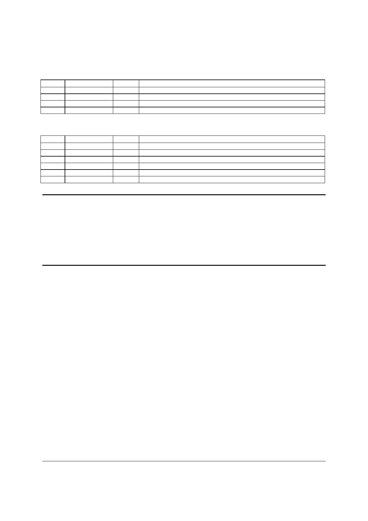
Table 67. SSI 4-pin Fan Header Pin-out (J7K1, J9A2, J9A3)
Pin Signal Name Type Description
1 Ground GND Ground is the power supply ground
2 12V Power Power supply 12 V
3 Fan Tach In FAN_TACH signal is connected to the BMC to monitor the fan speed
4 Fan PWM Out FAN_PWM signal to control fan speed
Table 68. SSI 6-pin Fan Header Pin-out (J1K1, J1K2, J1K4, J1K5)
Pin Signal Name Type Description
1 Ground GND Ground is the power supply ground
2 12V Power Power supply 12 V
3 Fan Tach In FAN_TACH signal is connected to the BMC to monitor the fan speed
4 Fan PWM Out FAN_PWM signal to control fan speed
5 Fan Presence In Indicates the fan is present
6 Fan Fault LED Out Lights the fan fault LED
Note: Intel
®
Corporation server boards support peripheral components and can contain a
number of high-density VLSI and power delivery components that need adequate airflow to cool.
Intel’s own chassis are designed and tested to meet the intended thermal requirements of these
components when the fully integrated system is used together. It is the responsibility of the
system integrator that chooses not to use Intel
®
developed server building blocks to consult
vendor datasheets and operating parameters to determine the amount of airflow required for
their specific application and environmental conditions. Intel Corporation cannot be held
responsible if components fail or the server board does not operate correctly when used outside
any of its published operating or non-operating limits.