Intel® Server Boards S5520HC, S5500HCV, and S5520HCT TPS Design and Environmental Specifications
Revision 1.8
Intel order number E39529-013
131
9.3.1 Processor Power Support
The server boards support the Thermal Design Power (TDP) guideline for Intel
®
Xeon
®
processors. The Flexible Motherboard Guidelines (FMB) were also followed to determine the
suggested thermal and current design values for anticipating future processor needs. The
following table provides maximum values for I
cc
, TDP power and T
CASE
for the compatible Intel
®
Xeon
®
Processor 5500 series.
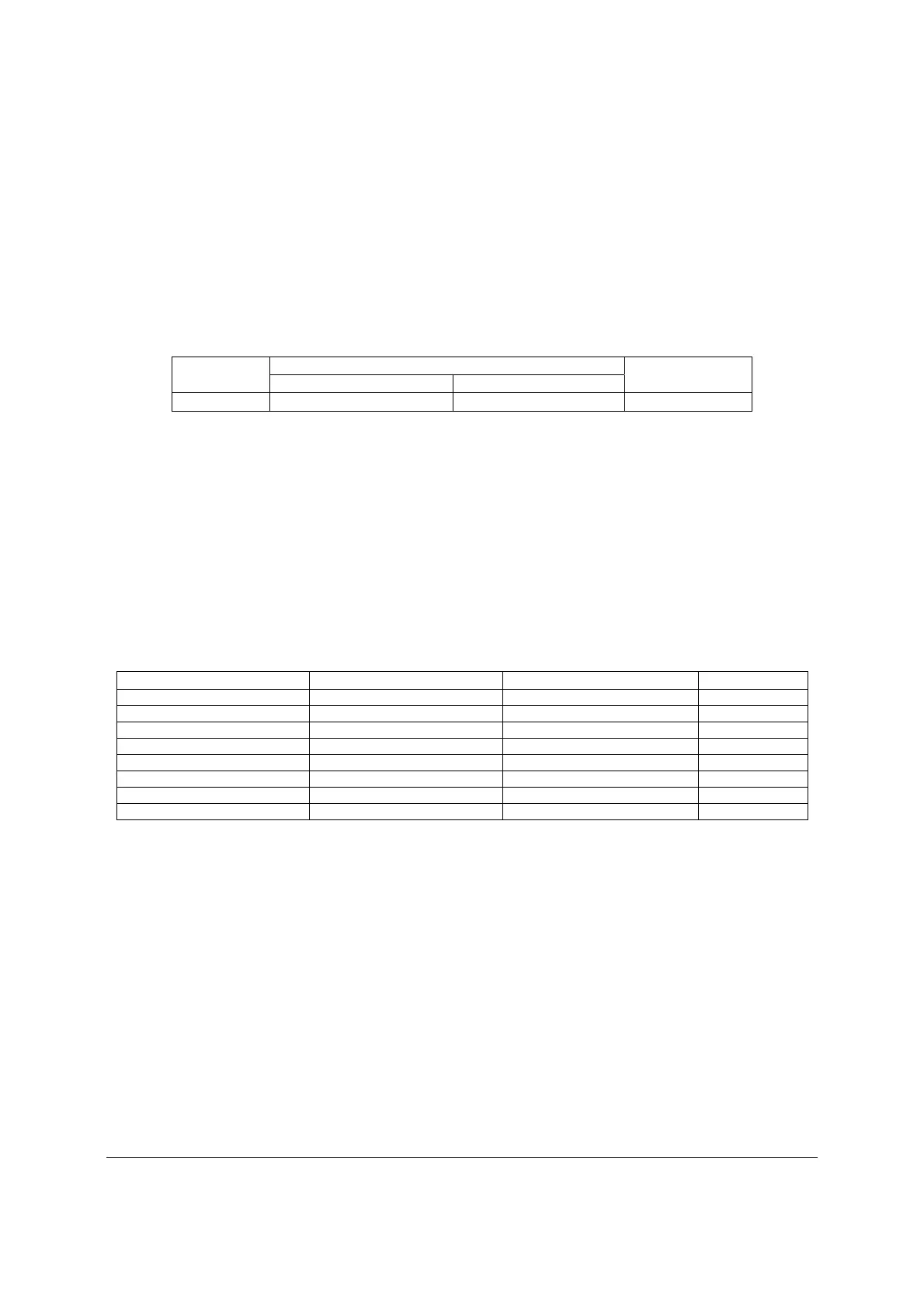
Table 73. Intel
®
Xeon
®
Processor Dual Processor TDP Guidelines
TDP Power
Max Tcase
Icc Max
Thermal Profile A Thermal Profile B
95 W
75 ℃ 81 ℃
120 A
9.4 Power Supply Output Requirements
This section is for reference purposes only. The intent is to provide guidance to system
designers to determine a power supply to use with these server boards. This section specifies
the power supply requirements Intel used to develop a power supply for its 5U server system.
The combined power of all outputs should not exceed the rated output power of the power
supply. The power supply must meet both static and dynamic voltage regulation requirements
for the minimum loading conditions.
Table 74. 670-W Load Ratings
Voltage Minimum Continuous Maximum Continuous Peak
+3.3 V 1.0 A 24 A
+5 V 2.0 A 30 A
+12 V1 0.5 A 16 A 18 A
+12 V2 1.0 A 16 A 18 A
+12 V3 0.5 A 31 A 33 A
+12 V4 1.0 A 16 A 18 A
-12 V 0 A 0.5 A
+5 VSB 0.1 A 3.0 A 5 A
1. Maximum continuous total output power must not exceed 670 W.
2. Maximum continuous load on the combined 12-V output must not exceed 48 A.
3. Peak load on the combined 12-V output must not exceed 52 A.
4. Peak total DC output power must not exceed 730 W.
5. For 12 V, peak power and current loading are supported for a minimum of 12 seconds.
6. For 5 VSB, 5 VSB must withstand 5 A for 500 ms under the first turn-on condition.
7. Combined 3.3 V and 5 V power must not exceed 170 W.
9.4.1 Grounding
The output ground of the pins of the power supply provides the output power return path. The
output connector ground pins are connected to the safety ground (power supply enclosure).
9.4.2 Stand-by Outputs
The 5 VSB output should be present when an AC input is greater than the power supply turn-on
voltage is applied.