Connector/Header Locations and Pin-outs Intel® Server Boards S5520HC, S5500HCV, and S5520HCT TPS
Revision 1.8
Intel order number E39529-013
110
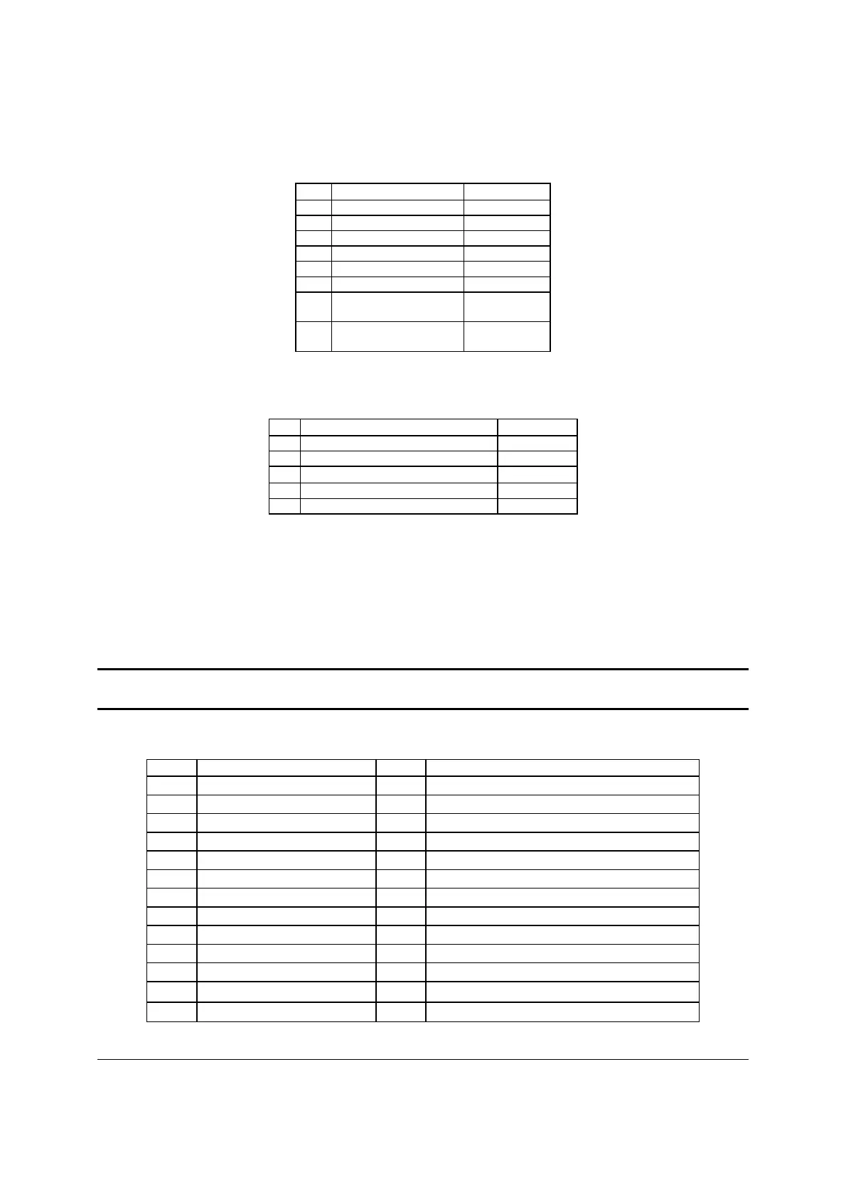
Table 49. CPU 2 Power Connector Pin-out (J9K1)
Pin Signal Color
1 GND of Pin 5 Black
2 GND of Pin 6 Black
3 GND of Pin 7 Black
4 GND of Pin 8 Black
5 +12 Vdc CPU2 Yellow/black
6 +12 Vdc CPU2 Yellow/black
7 +12 Vdc
DDR3_CPU2
Yellow/black
8 +12 Vdc
DDR3_CPU2
Yellow/black
Table 50. Power Supply Auxiliary Signal Connector Pin-out (J9K2)
Pin Signal Color
1 SMB_CLK_FP_PWR_R Orange
2 SMB_DAT_FP_PWR_R Black
3 SMB_ALRT_3_ESB_R Red
4 3.3 V SENSE- Yellow
5 3.3 V SENSE+ Green
6.3 System Management Headers
6.3.1 Intel
®
Remote Management Module 3 Connector
A 34-pin Intel
®
RMM3 connector (J1C1) is included on the server boards to support the optional
Intel
®
Remote Management Module 3. These server boards do not support third-party
management cards.
Note: This connector is not compatible with the Intel
®
Remote Management Module (Intel
®
RMM) or the Intel
®
Remote Management Module 2 (Intel
®
RMM2).
Table 51. Intel
®
RMM3 Connector Pin-out (J1C1)
Pin Signal Name Pin Signal Name
1 3V3_AUX 2 RMII_MDIO
3 3V3_AUX 4 RMII_MDC
5 GND 6 RMII_RXD1
7 GND 8 RMII_RXD0
9 GND 10 RMII_RX_DV
11 GND 12 RMII_REF_CLK
13 GND 14 RMII_RX_ER
15 GND 16 RMII_TX_EN
17 GND 18 KEY (pin removed)
19 GND 20 RMII_TXD0
21 GND 22 RMII_TXD1
23 3V3_AUX 24 SPI_CS_N
25 3V3_AUX 26 NC (spare)