Technical Reference
57
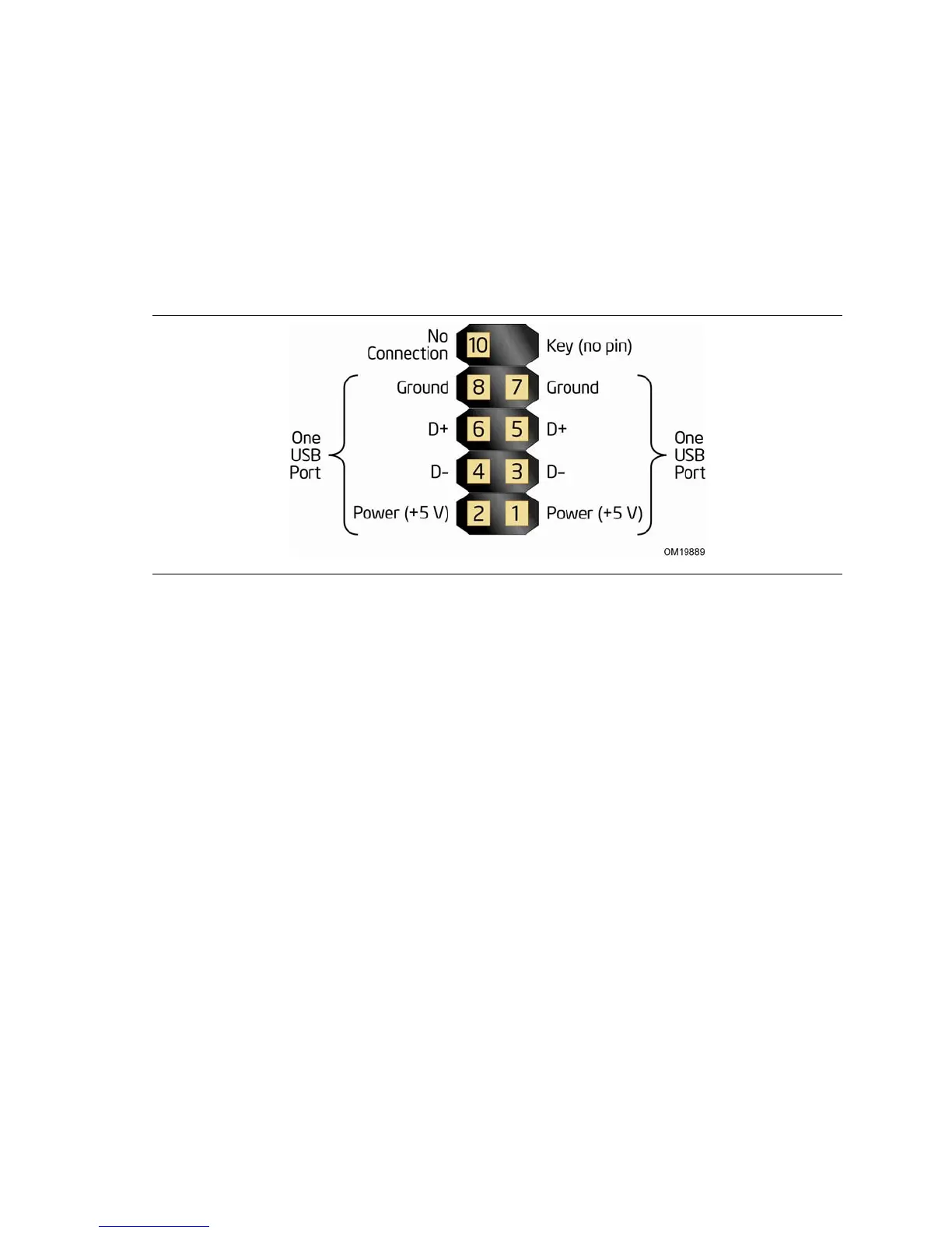
2.7.2.5 Front Panel USB Headers
Figure 15 is a connection diagram for the front panel USB headers.
#
INTEGRATOR’S NOTES
• The +5 V DC power on the USB headers is fused.
• Pins 1, 3, 5, and 7 comprise one USB port.
• Pins 2, 4, 6, and 8 comprise one USB port.
• Use only a front panel USB connector that conforms to the USB 2.0 specification
for high-speed USB devices.
Figure 15. Connection Diagram for Front Panel USB Headers