Installing and Replacing Desktop Board Components
27
How to Remove the Processor
To remove the processor, follow these instructions:
1. Observe the precautions in “Before You Begin” (see page 21).
2. Disconnect the processor fan cable.
3. Detach the fan heatsink clips.
4. Raise the socket handle completely.
5. Remove the processor.
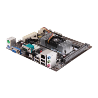
How to Install Memory
You can install from 32 MB to 512 MB of memory in the DIMM sockets. The board has two
DIMM sockets arranged as banks 0 and 1. As shown in Figure 11 on page 28, the DIMM socket
closest to the processor is for bank 0.
The desktop board supports the following memory features:
• 168-pin, 3.3 V DIMMs with gold-plated contacts
• 100 MHz, 4-clock, unbuffered SDRAM DIMMs
• Non-ECC (64-bit) memory
• A minimum of 32 MB of memory; a maximum of 512 MB of memory
For optimal video performance, install at least 64 MB of memory.
• Module sizes: 16 MB, 32 MB, 64 MB, 128 MB, and 256 MB
• DIMMs with Serial Presence Detect (SPD) data structure or non-SPD DIMMs
CAUTION
It is highly recommended that SPD DIMMs be use. This allows the BIOS to read the SPD data
and program the chipset to accurately configure memory settings for optimum performance. If
non-SPD memory is installed, the BIOS will attempt to correctly configure the memory settings,
but performance and reliability may be impacted.
✏
NOTE
Since some of the system memory is dedicated to video, install at least 64 MB of memory for
optimal video performance or if using the Windows NT
†
4.0 operating system.
The desktop board supports single- or double-sided DIMMs in the following sizes:
DIMM Size Non-ECC Configuration
16 MB 2 Mbit x 64
32 MB 4 Mbit x 64
64 MB 8 Mbit x 64
128 MB 16 Mbit x 64
256 MB 32 Mbit x 64