Technical Reference
61
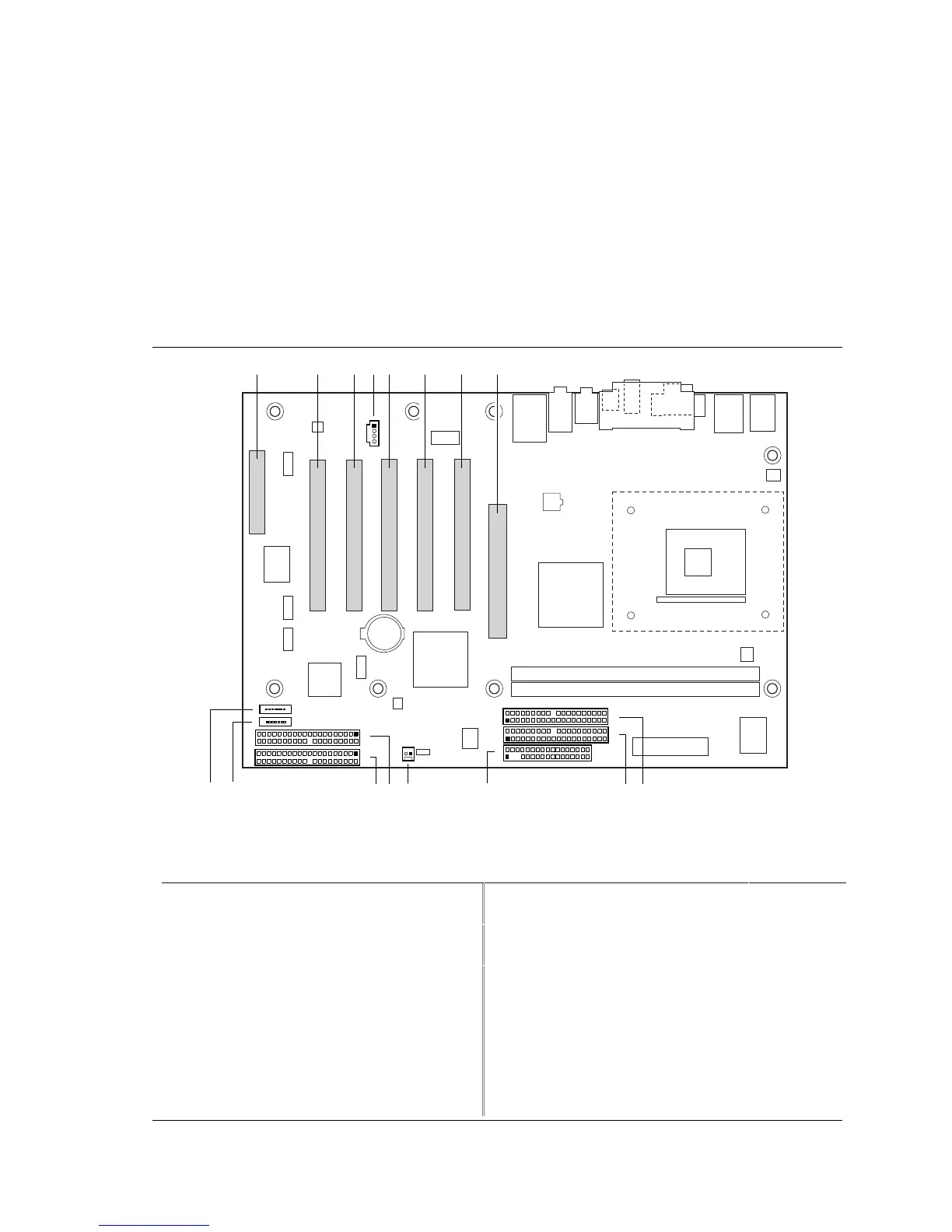
2.8.2.3 Add-in Board and Peripheral Interface Connectors
Figure 14 shows the location of the add-in board and peripheral connectors for the Desktop Board
D845PEBT2. Note the following considerations for the PCI bus connectors:
• All of the PCI bus connectors are bus master capable.
• The SMBus is routed to PCI bus connector 1 or 2 depending on the board’s AA number labeled
on the board’s front right corner (see section 2.8.2.1 on page 57). This enables PCI bus add-in
boards with SMBus support to access sensor data on the Desktop Board D845PEBT2. The
specific SMBus signals are as follows:
The SMBus clock line is connected to pin A40
The SMBus data line is connected to pin A41
1
2
33
34
1
2
40
39
1
2
40
39
I
JK
LP O
1
4
1
7
1
A B C E G
D
OM15034
HF
1
7
1
2
40
39
1
2
40
39
MN
Item
Description
For more
information
see:
Item Description
For more
information
see:
A CNR (optional) Table 36 I Secondary IDE [white] Table 41
B PCI bus connector 5 Table 37 J Primary IDE [black] Table 41
C PCI bus connector 4 Table 39 K Diskette drive Table 40
D ATAPI-style CD-ROM Table 37 L SCSI LED Table 42
E PCI bus connector 3 Table 37 M Secondary IDE RAID [blue]
(optional)
Table 43
F PCI bus connector 2 Table 37 N Primary IDE RAID [blue]
(optional)
Table 43
G PCI bus connector 1 Table 37 O Primary SATA/SATA RAID
(optional)
Table 44
H AGP Table 38 P Secondary SATA/SATA RAID
(optional)
Table 44
Figure 14. D845PEBT2 Add-in Board and Peripheral Interface Connectors