Intel Desktop Board DG41TY Product Guide
48
Chassis Intrusion Header
Figure 21, E on page 45 shows the location of the chassis intrusion header. This
header can be connected to a mechanical switch on the chassis to detect if the chassis
cover is removed.
Table 11 shows the pin assignments for t
he chassis intrusion header.
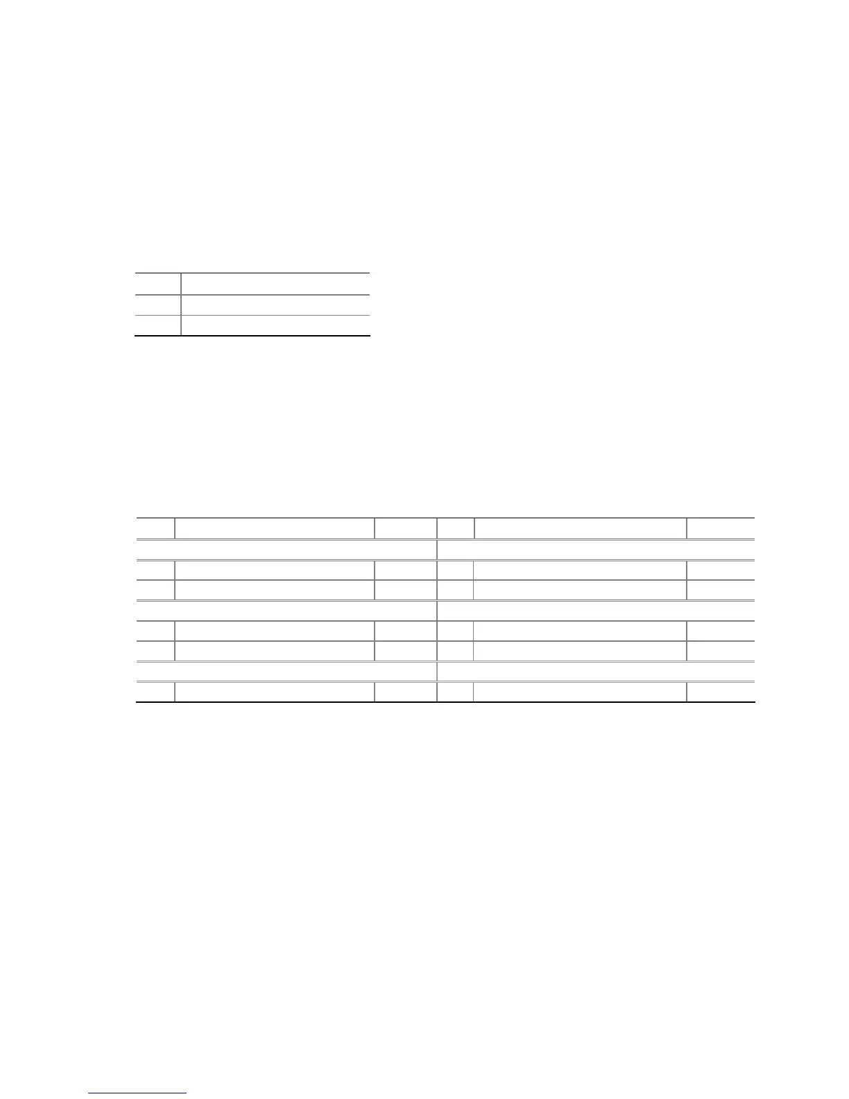
Table 11. Chassis Intrusion Header
Pin Description
1 Intruder
2 Ground
Front Panel Header
Before connecting to the front panel header, observe the precautions in "Before You
Begin" on page 27. See Figure 21, F on page 45 for the location of the multi-colored
front panel
header.
Table 12 shows the pin assignments for t
he front panel header.
Table 12. Front Panel Header
Pin Description In/Out
Pin Description In/Out
Hard Drive Activity LED Power LED
1 Hard disk LED pull-up to +5 V
Out 2 Front panel green LED Out
3 Hard disk active LED Out 4 Front panel yellow LED Out
Reset Switch On/Off Switch
5 Ground 6 Power switch In
7 Reset switch In 8 Ground
Power Not Connected
9 Power Out 10 No pin