Technical Reference
61
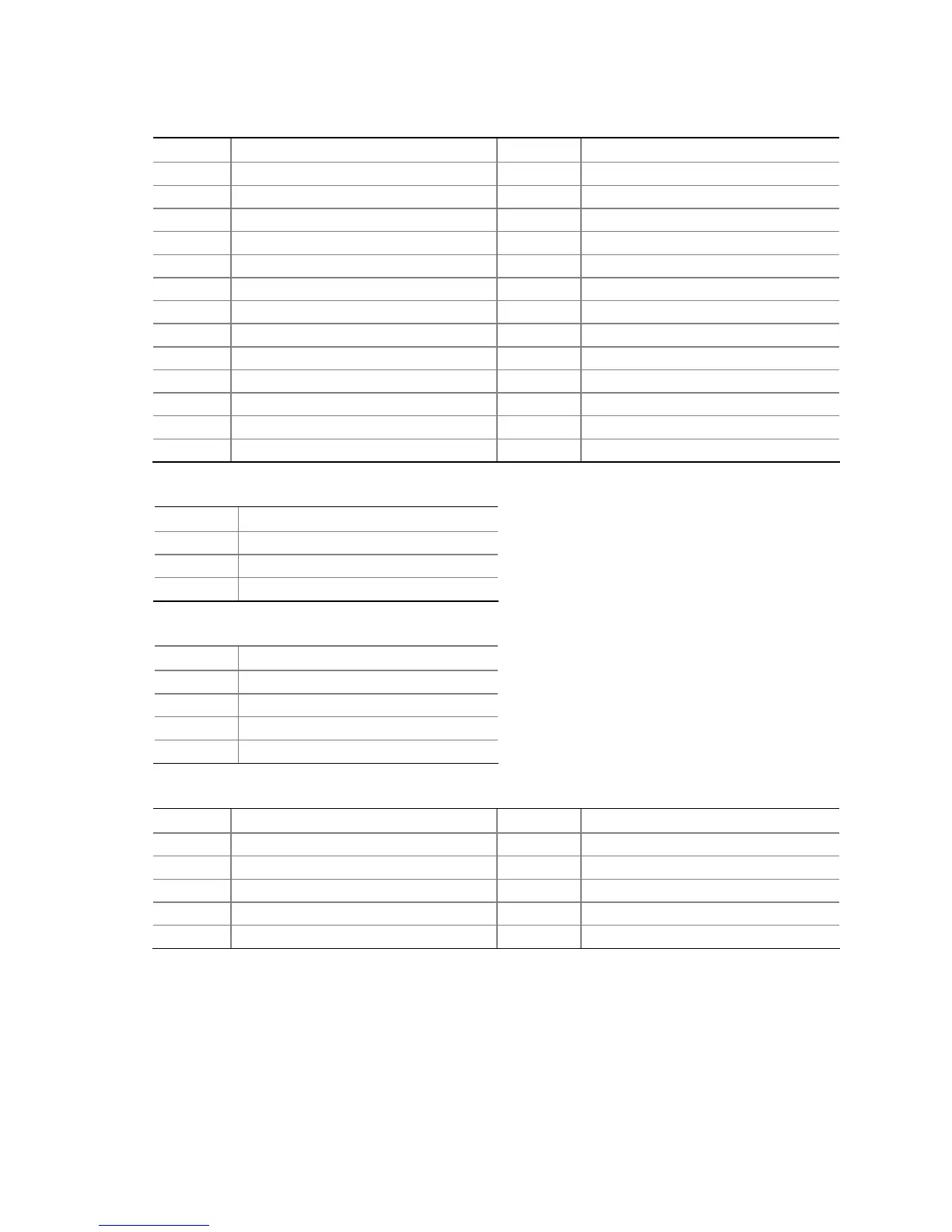
Table 23. Parallel Port Header
Pin Signal Name Pin Signal Name
1 STROBE# 2 AUTOFD#
3 PD0 4 FAULT#
5 PD1 6 INIT#
7 PD2 8 SLCTIN#
9 PD3 10 Ground
11 PD4 12 Ground
13 PD5 14 Ground
15 PD6 16 Ground
17 PD7 18 Ground
19 ACK# 20 Ground
21 BUSY 22 Ground
23 PERROR 24 Ground
25 SELECT 26 Key (no pin)
Table 24. Front and Rear Chassis Fan Headers
Pin Signal Name
1 Control
2 +12 V
3 Tach
Table 25. Processor Fan Header
Pin Signal Name
1 Ground
2 +12 V
3 FAN_TACH
4 FAN_CONTROL
Table 26. Front Panel Audio Header
Pin Signal Name Pin Signal Name
1 [Port 1] Left channel 2 Ground
3 [Port 1] Right channel 4 PRESENCE# (Dongle present)
5 [Port 2] Right channel 6 [Port 1] SENSE_RETURN
7 SENSE_SEND (Jack detection) 8 Key (no pin)
9 [Port 2] Left channel 10 [Port 2] SENSE_RETURN