722960-002 19
Intel
®
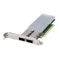
Ethernet Network Adapter E810-CQDA2T
User Guide
Users can also run ethtool -T <interface name> to show the PTP clock number.
# ethtool -T <interface name>
PTP Hardware Clock: 7
The E810 only has one hardware timer shared between all ports. As a result, users find the PTP clock
number only on Port 0.
If users need to use bonding or DPDK, do not use Port 0, as this prevents the use of Linux PHC API for
the device. A better solution is to use any other port for this functionality or to use a virtual function for
DPDK.
4.2 DPLL Priority
The E810-CQDA2T automatically switches reference inputs according to the default DPLL priority list, as
shown in Tab l e 7 .
where:
Note: The DPLL priority list can be changed. See Section 4.11, “Advanced DPLL Configuration”.
Note: From firmware version 4.20 or newer, the DPLL priority list and the DPLL configuration
parameters have been change to meet the ITU-T specs. The firmware will update the needed
parameters based on the incoming timing signals. SDP20 is expecting a 10 MHz signal.
Note: The input references are checked to ensure that they meet specified criteria before they are
fed to the DPLL. Each reference has several monitoring circuits and the one of particular
interest is called Precise Frequency Monitor (PFM). By default, input reference is measured in
PFM for 10 seconds to avoid disqualifying a reference with jitter/wander, which is still
acceptable by standards. This requirement originates from Telcordia GR-1244 standard.
Though this requirement is not used in ITU specs, many telecom customers find this feature
very useful. Only inputs that meet this 10 seconds of acceptable input are be seen as “valid”.
All others are be seen as “invalid”.
Pin index = DPLL device physical pin index
EEC - DPLL0 = Ethernet equipment clock source from DPLL0 for frequency adjustments.,
glitchless.
PPS - DPLL1 = 1PPS generation from DPLL1 for phase adjustments. Glitches allowed. Slower
locking.