Intel
®
Ethernet Network Adapter E810-CQDA2T
User Guide
48 722960-002
5.4 Boundary Clock Configuration
5.4.1 External Connections
5.4.2 Boundary Clock Notes
• For visibility, users might want to enable 1PPS on the SMA1.
• If users want to synchronize the DPLL to the E810 PHC, they must enable the appropriate SDP pin,
as there are two DPLLs: DPLL0 drives the external clock source of the E810 controller, while DPLL1
drives the SMA outputs.
• If users want to synchronize DPLL1 to ptp4l, then they must use SDP20.
• SMA1 Tx and U.FL1 Tx is not a supported configuration on the E810-CQDA2T.
5.4.3 Software Configuration
Before proceeding, it is recommended to set all SDP pins and U.FL to off (see Section 4.0).
1. Set interface device (only top command is essential):
# export ETH=`grep 000e /sys/class/net/*/device/subsystem_device | awk -F"/"
‘{print $5}' | head -n 1’ (port0)
# export ETH1=`grep 000e /sys/class/net/*/device/subsystem_device | awk -F"/"
‘{print $5}' | head -n 2 | tail -n +2’ (port1)
2. Set periodic output on SDP20 to 10 MHz (to synchronize the DPLL1 to the E810 PHC synced by
ptp4l):
# echo 1 0 0 0 100 > /sys/class/net/$ETH/device/ptp/ptp*/period
and set SDP22 (to synchronize the DPLL1 to the E810 PHC synced by ptp4l):
# echo 2 0 0 1 0 > /sys/class/net/$ETH/device/ptp/ptp*/period
Note: DPLL only syncs to SDP20/SDP22 if it is the higher priority. Setting SDP20 is the preferred
method for synchronizing 1PPS outputs.
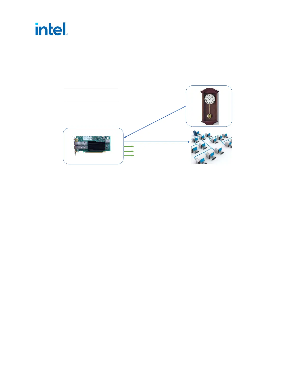
Figure 9. External Connections: Boundary Clock Configuration
E810-CQDA2T
Grand Leader
Blue = ptp4l
Green = Optional 1PPS output
Leader
Port0
Port1
SMA1
SMA2
U.FL1
U.FL2