On-board Connector/Header Overview Intel® Server Board S2600CO Family TPS
Revision 1.4
Intel order number G42278-004
92
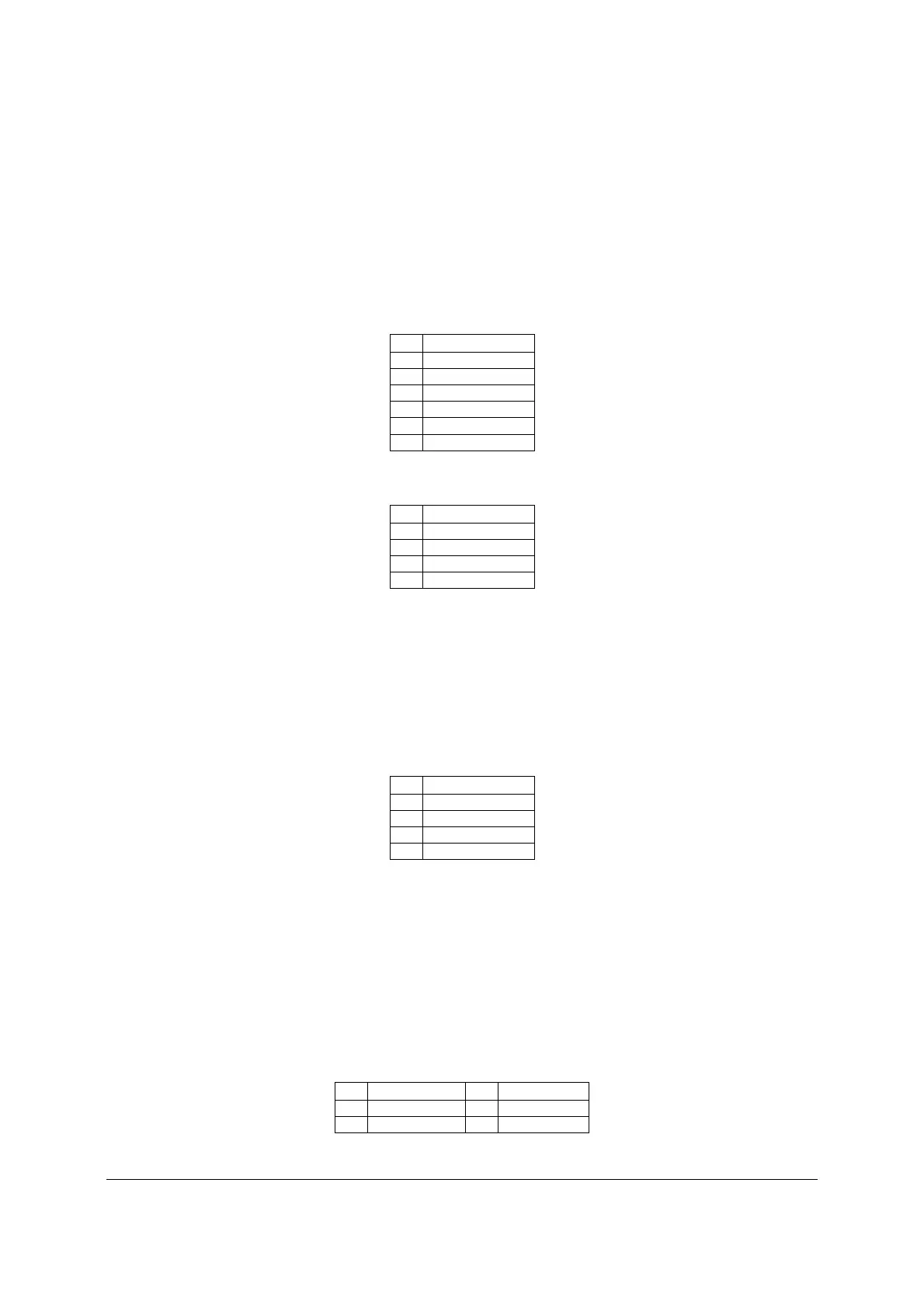
8.5.1 System FAN Connectors
The server board provides support for seven system cooling fans. Each connector is monitored
and controlled by on-board platform management. On the server board, each system fan
connector is labeled SYS_FAN_#, where # = 1 thru 7. The six system cooling fan connectors
near the front edge of the board (SYS_FAN_1 to SYS_FAN_6 are 6-Pin connectors; the one
system cooling fan near rear edge of the board is a 4-Pin connectors (SYS_FAN_7). Following
table provides the pin-out for all system fan connectors.
Table 47. 6-pin System FAN Connector Pin-out (SYS_FAN_1 to SYS_FAN_6)
Pin
Signal Description
1 GND
2 12V
3 TACH
4 PWM
5 PRSNT
6 FAULT
Table 48. 4-pin System FAN Connector Pin-out (SYS_FAN_7)
Pin
Signal Description
1 GND
2 12V
3 TACH
4 PWM
8.5.2 CPU FAN Connector
The server board also provides support for two CPU cooling fans. Each 4-pin connector is
monitored and controlled by platform management. On the server board each CPU fan
connector is labeled as CPU_1FAN and CPU_2FAN. The following table provides the pin-out
for both fan connectors.
Table 49. CPU Fan Connector Pin-out (CPU_1 FAN and CPU_2 FAN)
Pin
Signal Description
1 GND
2 12V
3 TACH
4 PWM
8.6 Serial Port Connectors
The server board includes two serial port connectors.
8.6.1 Serial Port A connector (DB9)
Serial-A is an external RJ45 type connector labeled as SERIAL_A and has the following pin-out
configuration:
Table 50. Serial Port A Connector Pin-out (SERIAL_A)
Pin Signal Name Pin
Signal Name
1 SPA_DCD 2 SPA_SIN_N
3 SPA_OUT_N 4 SPA_DTR

 Loading...


