Intel® Server Board S2600CO Family TPS On-board Connector/Header Overview
Revision 1.4
Intel order number G42278-004
83
8.1.3 PCIe Card Power Connectors
The server board includes one 4-pin power connectors that provide support for add-in cards that
require more power than is supported from the PCIe slots direct. The connector is labeled as
OPT_12V_PWR.
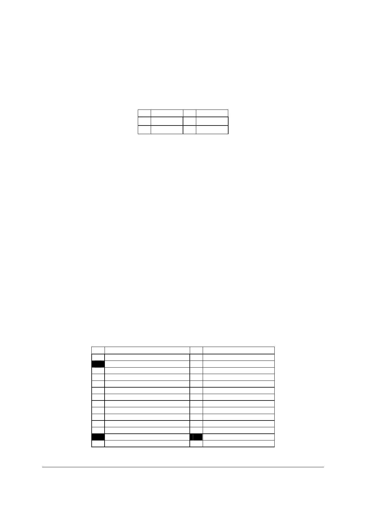
Table 25. PCIe Card Power Connector Pin-out (“OPT_12V_PWR”)
Pin Signal name
Pin
Signal name
1 GND 3 +12V
2 GND 4 +12V
8.2 Front Panel Headers and Connectors
The server board includes several connectors that provide various possible front panel options.
This section provides a functional description and pin-out for each connector.
8.2.1 SSI Front Panel Header
Included on the front edge of the server board is a 30-pin SSI compatible front panel header
which provides for various front panel features including:
Power/Sleep Button
System ID Button
System Reset Button
NMI Button
NIC Activity LEDs
Hard Drive Activity LEDs
System Status LED
System ID LED
On the server board, this header is labeled “SSI FRONT PANEL”. The following table provides
the pin-out for this header.
Table 26. SSI Front Panel Header Pin-out (“SSI Front Panel”)
Pin Signal Name Pin
Signal Name
1 SB3.3V 2 SB3.3V
KEY 4 SB5V
5 Power LED Cathode 6 System ID LED Cathode
7 3.3V 8 System Fault LED Anode
9 HDD Activity LED Cathode 10 System Fault LED Cathode
11 Power Switch 12 NIC#1 Activity LED
13 GND (Power Switch) 14 NIC#1 Link LED
15 Reset Switch 16 I
C SDA
17 GND (Reset/ID/NMI Switch) 18 I
C SCL
19 System ID Switch 20 Chassis Intrusion
21 Pull Down 22 NIC#2 Activity LED
23 NMI to CPU Switch 24 NIC#2 Link LED
KEY KEY
27 NIC#3 Activity LED 28 NIC#4 Activity LED

 Loading...


