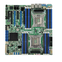
Intel® Server Board S2600CO Family TPS List of Tables
Revision 1.4
Intel order number G42278-004
ix
Table 40. RMM4_Lite Connector Pin-out (RMM4_Lite) ............................................................... 90
Table 41. RMM4_NIC Connector Pin-out (RMM4_NIC) .............................................................. 90
Table 42. TPM Connector Pin-out (TPM) ..................................................................................... 90
Table 43. PMBus* Connector Pin-out (SMB_PMBUS*) .............................................................. 91
Table 44. Chassis Intrusion Header Pin-out (CHAS INTR) ......................................................... 91
Table 45. Chassis Instrusion Header State Description .............................................................. 91
Table 46. IPMB Connector Pin-out (IPMB) .................................................................................. 91
Table 47. 6-pin System FAN Connector Pin-out (SYS_FAN_1 to SYS_FAN_6) ........................ 92
Table 48. 4-pin System FAN Connector Pin-out (SYS_FAN_7) .................................................. 92
Table 49. CPU Fan Connector Pin-out (CPU_1 FAN and CPU_2 FAN) ..................................... 92
Table 50. Serial Port A Connector Pin-out (SERIAL_A) .............................................................. 92
Table 51. Serial-B Connector Pin-out (SERIAL_B) ...................................................................... 93
Table 52. Rear VGA Video Connector Pinout (VGA) ................................................................... 93
Table 53. HSBP 4-PIN I
2
C BUS Connector pin out (FAN BOARD_I
2
C) ..................................... 94
Table 54. IEEE 1394b Connector pin out ..................................................................................... 94
Table 55. Server Board Jumpers (J1E2, J1E3, J1E4, J1E6, J1J2) ............................................. 95
Table 56. System Status LED .................................................................................................... 103
Table 57. POST Code Diagnostic LEDs .................................................................................... 104
Table 58. Server Board Design Specifications........................................................................... 105
Table 59. MTBF Estimate ........................................................................................................... 106
Table 60. Over Voltage Protection Limits ................................................................................... 107
Table 61. Loading Conditions ..................................................................................................... 107
Table 62. Voltage Regulation Limits ........................................................................................... 108
Table 63. Transient Load Requirements .................................................................................... 108
Table 64. Capacitive Loading Conditions ................................................................................... 109
Table 65. Ripples and Noise ...................................................................................................... 109
Table 66. Output Voltage Timing ................................................................................................ 110
Table 67. Turn On/Off Timing ..................................................................................................... 111
Table 68. Intel
®
Server Chassis P4000M family Features ......................................................... 117
Table 69. BMC Core Sensors ..................................................................................................... 122
Table 70. Chassis-specific Sensors ........................................................................................... 133
Table 71. Fan Domain Definition ................................................................................................ 134
Table 72. Power Supply Support ................................................................................................ 136
Table 73. Server Platform Services Firmware Health Event ..................................................... 138
Table 74. Node Manager Health Event ...................................................................................... 139
Table 75. POST Progress Code LED Example ......................................................................... 140
Table 76. Diagnostic LED POST Code Decoder ....................................................................... 141
Table 77. MRC Progress Codes ................................................................................................. 143
Table 78. MRC Fatal Error Codes .............................................................................................. 143
Table 79. POST Error Codes and Messages ............................................................................. 145
Table 80. POST Error Beep Codes ............................................................................................ 150

 Loading...