22 Intel® Server Board S3420GP User Guide
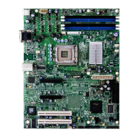
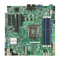
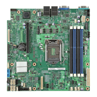
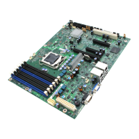
Figure 2. Server Board Connector and Component Locations
F. Slot 5, PCI Express* Gen2 x8
(x8 connector)
V. System FAN 1 (Intel
®
Server
Board S3420GPLX and
S3420GPLC)
G. Slot 6, PCI Express* Gen2 x8
(x16 connector)
W. IPMB (Intel
®
Server Board
S3420GPLX and S3420GPLC)
H. CMOS battery X. SATA_SGPIO
I. Ethernet and Dual USB Combo Y. HSBP (Intel
®
Server Board
S3420GPLX and S3420GPLC)
J. Ethernet and Dual USB Combo Z. USB Floppy
K. System FAN 4 AA. Six SATA ports
L. Video port BB. Internal USB Connector (One
for Internal USB header on Intel
®
Server Board S3420GPV)
M. External serial port CC. Front panel connector
N. Main power connector DD. Internal serial ports
O. CPU power connector
P. DIMM slots (4 slots on Intel
®
Server Board S3420GPV)
 Loading...


