24 Intel® Server Board S3420GP User Guide
Figure 3. Configuration Jumpers Location
Back Panel Connectors
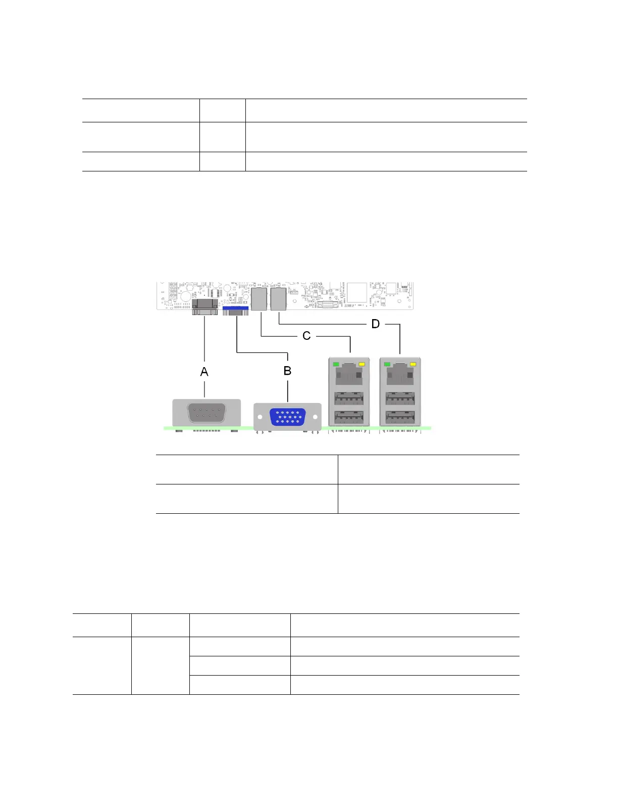
Figure 4. Back Panel Connectors
The NIC LEDs at the right and left of each NIC provide the following information.
J1F1: ME Force Recovery 1-2 These pins should have a jumper in place for normal system
operation. (Default)
2-3 ME force update mode
Jumper Name Pins What will occur during a system reset..
A. Serial Port A C. NIC Port 1 (1 Gb) and Dual USB Port
Connector
B. Video D. NIC Port 2 (1 Gb) and Dual USB Port
Connector
Table 3. NIC LED Descriptions
NIC Color LED State Description
Left Green Off LAN link is not established.
On LAN link is established.
Blinking LAN activity is occurring.