Intel® Storage System SSR212MA Feature Summary
Revision 1.4 5
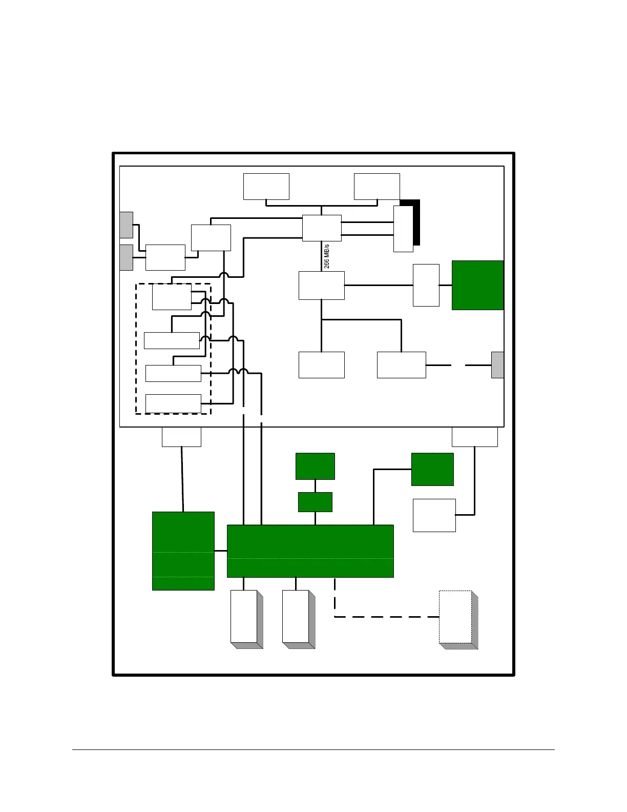
1.1 System Components
A block diagram of the storage system functional components is shown below.
Low Voltage
Intel® Xeon®
processor
SATA
HDD
#1
EMPTY
PCI Slot #3
Intel® SRCS28X
#2
Intel® SRCS28X
#1
(EMPTY)
Intel®
E7520 MCH
Intel®
82801ER
I/O Controller
Hub 5-R
Intel® 6700
PXH
Intel®
PRO/1000
SATA
HDD
#2
SATA
HDD #12
Hot Swap SATA Backplane
Power Supply
Enclosure
(PDB, 60 mm Fan)
2x 500 Watt
(“1+1” Power Supply
Modules)
0 MB
Intel® Server Board SE7520JR2
Up to 12 optional 1.5 or 3.0 Gb/s
SATA drives
64/133 (1066 MB/s)
IDE
Header
ATA100
800 MHz (6.4 GB/s)
RJ
45
DDR2-400 Bus A
DDR2-400 Bus B
RJ
45
Front Panel
Power, Fault
ID LED’s.
Rear Panel
mounted
Power, Reset
switches.
Power
Supply
Header
expandable to 16 GB with 6x 512 Mb
technology DIMMs
5x 40mm
Fans
PCI-Express x8
(4.2 GB/s)
x6
x6
Disk On Module
(DOM)
Transition
Board
Intel®
Management
Module
LPC
Intel® 6700
PXH
Riser
Front
PanelHeader
National
Semiconductor*
PC87427 Super
I/O
RJ
45
serial
Figure 2. Intel
®
Storage System SSR212MA Block Diagram