System Interconnection Intel® Storage System SSR212MA
32 Revision 1.4
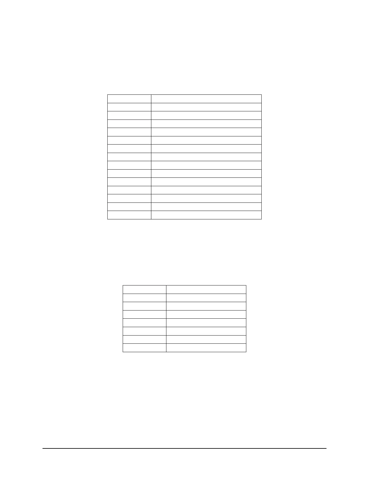
5.3.4 Front Panel Connector
The following table defines the pin-outs of the 1x14 Front Panel connector.
Table 16. Front Panel Power Connector
Pin Signal Name
1 GND
2 COM_CTS
3 COM_RX
4 COM_TX
5 COM_RTS
6 GND
7 +5V_OPS
8 +5V_OPS
9 I2C_SDA_OPS
10 I2C_SCL_OPS
11 LED1_OPS/SPARE1 (power)
12 LED2_OPS/SPARE2 (fault)
13 LED3_OPS/SPARE3 (ID)
14 GND
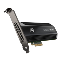
5.3.5 SATA Host I
2
C Header
The following table defines the pin-outs of the two 3-pin SATA Host I
2
C Headers.
Table 17. SATA Host I
2
C Header Pin-out
Pin Signal Name
1 I2C_SCL_A
2 GND
3 I2C_SDA_A
Pin Signal Name
1 I2C_SCL_B
2 GND
3 I2C_SDA_B