Intel® Storage System SSR212MA Feature Summary
Revision 1.4 11
• Vitesse* VSC055 (Enhanced Two-Wire Serial controller)
o Drive fault LED
o Drive presence detection
o I
2
C link to Intel® Server Board SE7520JR2
o 8× fan speed (tacho) input
o 2× PWM output
o 3 I/O signals to operator panel capable of driving LED’s
• CPLD (Altera* EPM3128ATC100-10)
o Alarm output
o Alarm event monitor (enclosure, disk drive and PSU status)
o Cooling module fault LED mounted to rear of backplane
o Software override capability through I
2
C
1.5.1 Fan Control
• PWM high-side drive configuration
• Fan tach filtering
• Protective diodes on all hot-swappable signal lines
1.5.2 Miscellaneous Functions
• I
2
C EEPROM for FRU data
• Chassis intrusion switch (slotted opto switch). However, SAN/IQ software does not
utilize this switch.
1.5.3 I
2
C Serial Bus Interface
The enclosure management controller supports four independent I
2
C interface ports with bus
speeds of up to 400 Kb/s.
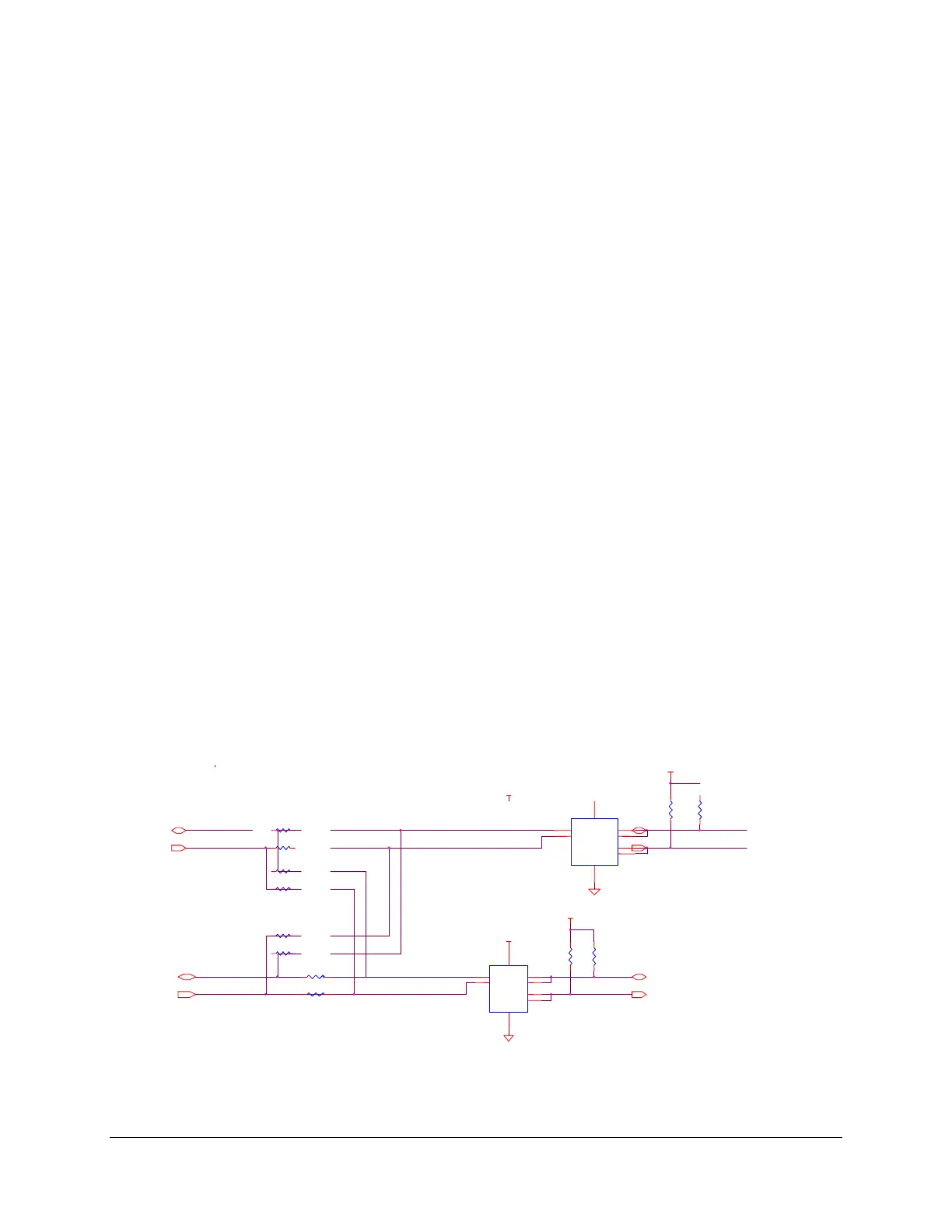
The figure below provides a block diagram of I
2
C bus connection implemented on the Storage
System SSR212MA SATA Hot Swap Backplane (HSBP).
Figure 5. SATA HSBP I
2
C Bus Connection Diagram
SCL
7
SDA
1
Vdd
8
T
3
RY
6
T
5
Vss
4
R
2
U
P82B96TD
I2C_SCL_OP
I2C_SDA_OP
+5
+5
I2C_SCL_A
I2C_SDA_
I2C_SCL_B_BU
+5V
R95
2K
1%
R9
2K
1%
I2C_SDA_B_BUF
R8 0R
5%
NO
R81 0R
5%
R76 0R
5%
I2C_SDA_BP
I2C_SCL_B
I2C Buffer for Ops
R8 0R0
5
NO
R77 0R
5%
NO
R80 0R0
5%
NO FIT
I2C_SCL_B
I2C_SDA_B
R88 0R0
5%
R85 0R0
5%
I2C_SDA_A_BUF
I2C_SCL_A_BUF
SCL
7
SDA
1
Vdd
8
T
3
R
6
T
5
Vss
4
RX
2
U7
P82B96T
+5V
R147
2K7
1%
R148
2K7
1%
I2C Buffer for Backplane