Chassis Bays Intel® Storage System SSR212MA
26 Revision 1.4
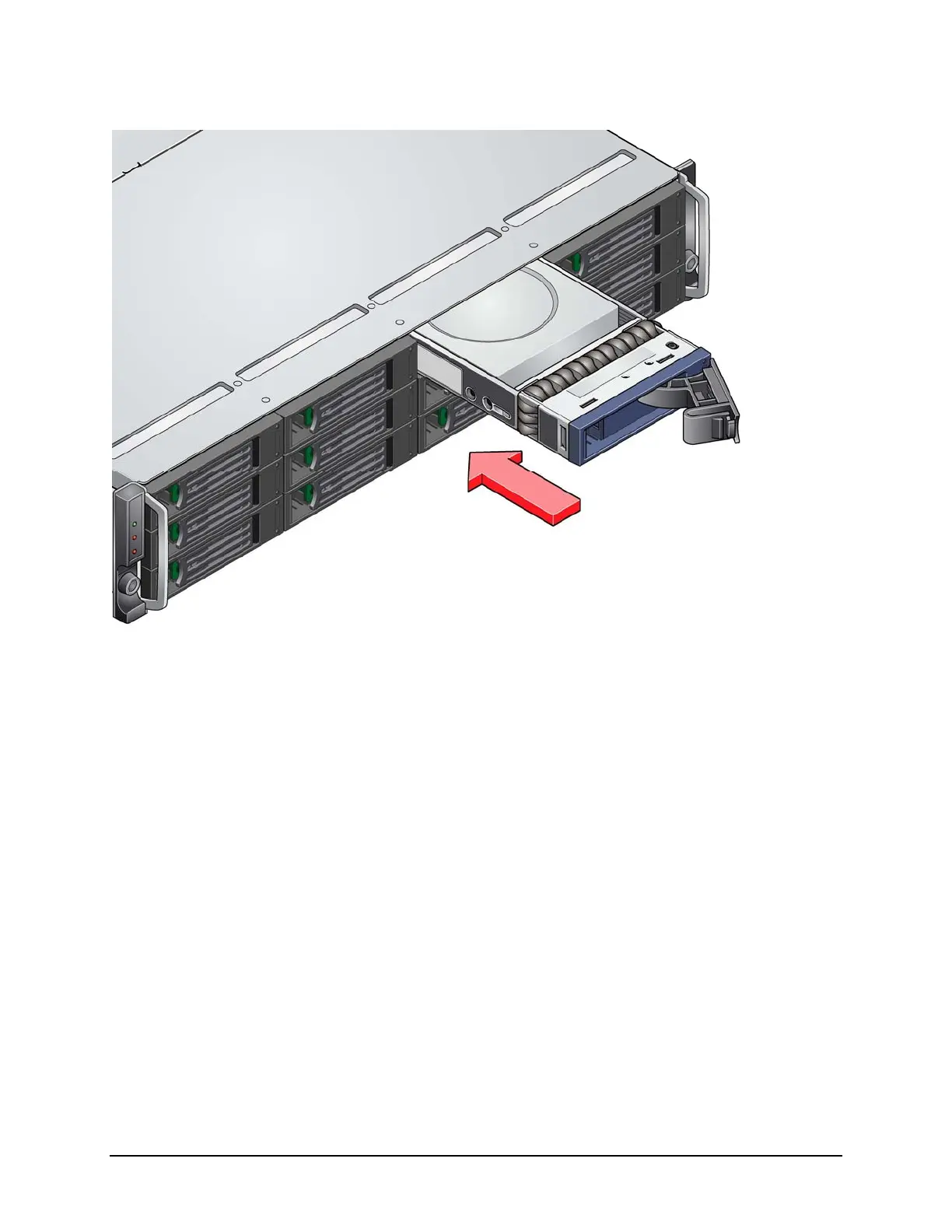
Figure 13. Hard Disk Drive Bays
4.1.1 Hard Disk Drive Carrier
Each hard drive used in the system must be mounted to a drive carrier, making insertion and
extraction of the drive from the chassis very simple. Each drive tray has its own dual purpose
latching mechanism that is used to both insert/extract drives from the chassis and lock the
carrier in place, and also has a safety locking mechanism to aid in the prevention of accidental
removal of a drive. After the drive is inserted and latched, the locking feature is enabled by
rotating the locking mechanism using the provided Torx* or “star” bit tool, such that the latch can
not be depressed to remove the drive. To remove the drive, turn the locking mechanism until the
latch can be depressed to remove the drive. Each drive carrier also supports a light pipe
providing a drive status indicator, located on the backplane, to be viewable from the front of the
chassis.