Do you have a question about the Interlogix ATS1201E and is the answer not in the manual?
Covers servicing, handling of the intrusion control panel, and screw installation for housing.
Provides instructions for safely connecting the mains power supply, including wiring and circuit breaker requirements.
Guides on safely removing and disposing of the product's rechargeable battery.
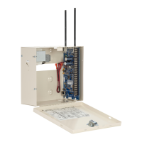
Details how to mount the unit securely on a flat, solid surface, including clearance requirements.
Explains proper earthing procedures for system components and cabinets, including connections and safety.
Details how to connect shielding for data cables to prevent interference and ensure system integrity.
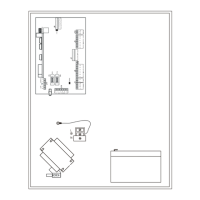
Explains how to configure DGP addresses using DIP switches for proper system identification.
Guides on connecting data gathering panels and arming stations via the system databus for communication.
Explains how zones and outputs are numbered for DGP addresses and system expansion.
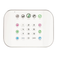
Steps to configure DGP settings using the Advisor Master control panel interface.
Details how to access and navigate the DGP's programming menu for configuration and status checks.
Allows configuration of DGP settings like address, battery load, mains check, and output modes.
Solves problems related to low or no auxiliary current and PSU faults, including resistor recommendations.
Covers voltage, current, and output specifications for the power supply, including battery capacity.
Includes end-of-line resistor, output type, housing details, and operating temperature/humidity.
| Type | Control Panel |
|---|---|
| Partitions | 2 |
| Users | 32 |
| Input Voltage | 16.5 VAC |
| Output Voltage | 12 VDC |
| Current Rating | 1 A |
| Frequency | 50/60 Hz |
| Zones | 8 |
| Power Supply Current | 500 mA |
| Operating Temperature | 0°C to 49°C |
| Compatibility | Interlogix devices |