Page 30
venting system).
If the existing venting system is a horizontal run, the
slope of that system will need to be changed. As
installed, that system required a downward slope of
¼” per foot toward the outside wall. The venting
system for FT boiler requires a slope of 3/8” per foot
back toward the boiler so that condensate will drain
back to the boiler and be eliminated. To change the
slope, the vent pipe hangers will need to be adjusted
or replaced.
The centerline of the ue on the FT boiler is 3.9” (99
mm) from the back of the boiler cabinet. The centerline
of the ue on the existing boiler is 9” (229 mm) from
the back of the boiler cabinet. If the FT boiler can be
installed so that its cabinet back is 5” (127 mm) further
forward from the back wall than the existing boiler,
then the FT boiler vent and the venting system will be
in alignment. If, however, the boiler location for the FT
boiler, with respect to the back wall, cannot be
changed, 45° oset ttings will be required to bring the
centerline of the FT vent forward to align with the
existing vent assembly.
The FT boiler has separate Combustion Air and Vent
connections. Using the Parts Kits indicated in the
following instructions, it can be connected with a PP
Concentric Vent System.
If this 5" oset in the venting system is required, it can
be achieved in 2 ways.
Option 1:
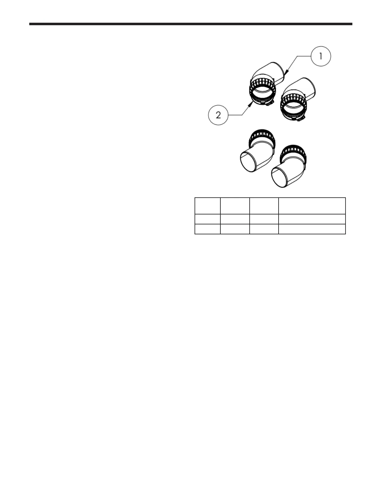
Assemble the elbows in an FT3001 Elbow
Kit to form two oset assemblies. Ensure that the
elbows bottom out and tighten the clamps.
Option 2:
Use 2 45° Duravent concentric elbows
(3PPC-E45) and install them in o-set fashion into the
concentric vention as described below.
Venting Assembly Process:
1)
Start the installation by installing only the 2
stainless to PP adapters of the P/N FT3002 Stub Out
Kit, directly in the FT boiler Combustion Air and Vent
sockets. Ensure that all connections bottom out and
tighten the clamps on the boiler vent connectors.
2)
If the above mentioned 5" oset is required, install
now the 2 pre-assembled o-set assemblies into each
stainless to PP adaptor. Then install the 2 PP lengths
into the Stub-out kit (FT3002)(Option 1 solution for
o-set).
Note:
Do not overtighten the connections until the
entire system is put together.
3)
If FT3001 Elbow kit is not required, the complete
Stub-out kit (FT3002) can be installed or o-set option
2 is selected, the length of the 2 PP portions can be
shortened; make sure to cut the same length from
each pipe. Do not cut more that 6-1/2" from each
pipe.
Assemble the parts in the following order:
4)
Insert the 3" stainless steel to PP adapters into the
2 3" vent connections on top of the FT Boiler until
they bottom out into the sockets.. Moisten the seals on
the sockets to make the insertion easier and to avoid
damaging the seals. Tighten the clamps on the boiler
FT3001 Oset Kit
ITEM
NUMBER
QUANTITY PART
NUMBER
DESCRIPTION
1 4 810014537 3˝ Dia 45° Elbow - Single Wall
2 4 810014538 3˝ Dia Locking Clamp