2 9
SECTION 5—REAR WHEELS/FRONT CASTORS
Removing/Installing/Repositioning the Castor Assemblies
NOTE: If replacing a front castor note the mounting position of the existing front
castor for installation of the new front castor.
NOTE: If repositioning front castors or replacing the existing front castor with a castor
of a different size, refer to Changing Front Seat
-
to
-
Floor Height paragraph to determine
the front castor position needed for the required front seat-to
-
floor height.
NOTE: Both front castors MUST be the same size and adjusted to the same height.
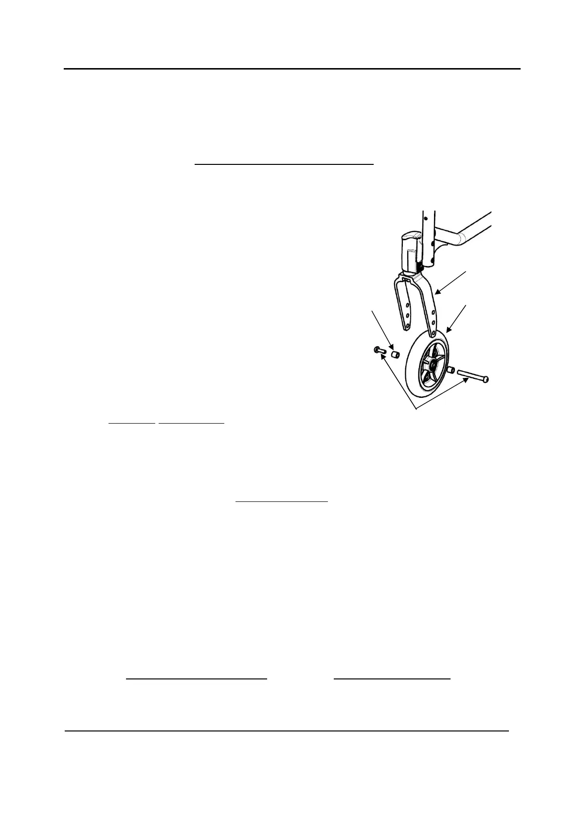
NOTE: For this procedure, refer to FIGURE 5.9.
Removing Front Wheel
1. Remove the mounting bolt (5 mm Allen key), axle
spacers (if present) that secure the front wheel to the fork.
2. Remove the wheel from the fork.
Installing Front Wheel
1. Using the mounting bolt (5 mm Allen key),
axle spacers (if present), secure the wheel to the
desired wheel mounting position.
2. Ensure fork stem is perpendicular to the flat surface.
Refer to Adjusting Castor Angle paragraph.
Adjusting Castor Angle (if so equipped)
IMPORTANT: Fixing screws may only be used once. Always use the dedicated spare
parts kit (SP1657713) for castor housing Standard.
Alternatively, the screws can be cleaned (remove old thread locking adhesive) and
reinstalled with new medium-strength thread locking adhesive (e.g.: LOCTITE® 243™ or
270™).
INFORMATION: Always refer to the liquid thread locking adhesive supplier’s
recommendations before applying on the screw.
NOTE: For this procedure, refer to FIGURE 5.10, next page.
1. Remove the two mounting screws (5 mm Allen key) that secure the castor housing
assembly to the wheelchair frame and the attachment plate.
IMPORTANT: To adjust the castor angle on both sides, use the spare parts kit (SP1657713)
consisted of 4 mounting pre-glued screws (M6x37mm) and 2 attachment plates.
2. Fit but not tighten the new attachment plate and the 2 mounting screws
3. Rotate the castor assembly to the desired angle.
Wheel
Axle Spacers
(if present)
Mounting Bolt
Fork