Optidrive Plus 3
GV
Compact - User Guide
14
www.invertek.co.uk
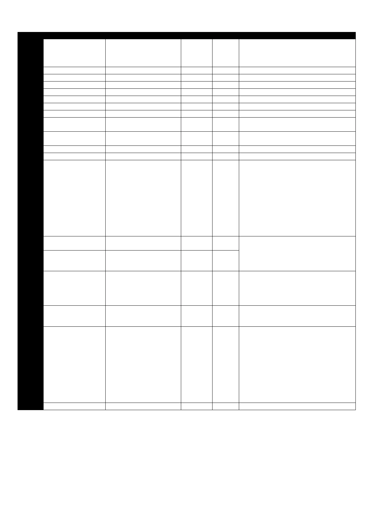
6.2. Parameter Group 2 - Extended parameters
Par. Description Range Units Default Explanation
P2-01
Digital input function
select
0 to 22 - 0
Defines the function of the digital inputs
depending on the control mode setting in P-12.
See section 7 Analog and Digital Input
Configurations for more information.
P2-02 Preset Speed 2 -P1-01 to P1-01 Hz 0.0 Sets jog / preset speed 2
P2-03 Preset Speed 3 -P1-01 to P1-01 Hz 0.0 Sets jog / preset speed 3
P2-04 Preset Speed 4 -P1-01 to P1-01 Hz 0.0 Sets jog / preset speed 4
P2-05 Preset Speed 5 -P1-01 to P1-01 Hz 0.0 Sets jog /preset speed 5
P2-06 Preset Speed 6 -P1-01 to P1-01 Hz 0.0 Sets jog / preset speed 6
P2-07 Preset speed 7 -P1-01 to P1-01 Hz 0.0 Sets jog / preset speed 7
P2-08 Preset speed 8 -P1-01 to P1-01 Hz 0.0 Sets jog / preset speed 8
P2-09 Skip frequency P1-02 to P1-01 Hz 0.
Centre point of skip frequency band set up in
conjunction with P2-10
P2-10 Skip frequency band 0.0 to P1-01 Hz 0.0
Width of skip frequency band centred on
frequency set in P2-09
P2-11 Reserved
P2-12 Reserved
P2-13
User Relay Output
Function Select
0 : Drive enabled
1 : Drive healthy
2 : Motor at target speed
3 : Motor Speed >0
4 : Motor speed >= limit
5 : Motor torque >= limit
6 : 2
nd
Analog Input >= limit
1
Selects the function assigned to the relay
output.
0 : Logic 1 when the drive is enabled (Running)
1: Logic 1 When no Fault condition exists on the
drive
2 : Logic 1 when the motor speed matches the
setpoint speed
3 : Logic 1 when the motor runs above zero
speed
Options 4 to 6 : the Digital output is enabled
using the level set in P2-14h and P2-14L
P2-14h
Relay Output Control
High Limit
0.0 to 200.0 % 100.0
With P2-13 = 4 to 6, the User Relay Output is
set to Logic 1 (+24V DC) when the value set in
P2-14h is exceeded, and returns to Logic 0 (0V)
when the selected value reduces below the
limit set in P2-12L
P2-14L
Relay Output Control
Low Limit
0.0 to 200.0 % 100.0
P2-15 Relay Output Mode
0 : Normally Open
1 : Normally Closed
- 0
Inverts the operating status of the User Relay
0 : Logic 1 = Relay Contacts Closed
1 : Logic 1 = Relay Contacts Open
The drive must be powered for the contacts to
close
P2-16
Zero Speed Holding
Time
0.0 to 60.0 s 0.2
Determines the time for which the drive output
is held at zero speed when stopping, before the
drive output is disabled
P2-17 Start Mode Select
Edge
EdgeEdge
Edge-
--
-r
rr
r
Auto
AutoAuto
Auto-0
-0-0
-0
Auto
AutoAuto
Auto-1
-1 -1
-1
to
5
55
5
- Auto-0
Edge-r : Following Power on or reset, the drive
will not start if Digital Input 1 remains closed.
The Input must be closed following a power on
or reset to start the drive.
Auto-0 : Following a Power On or Reset, the
drive will automatically start if Digital Input 1 is
closed.
Auto 1 to 5 : Following a Fault, the drive will
make up to 5 attempts to restart at 20 second
intervals. The drive must be powered down to
reset the counter
P2-18 Reserved - - No Function