8
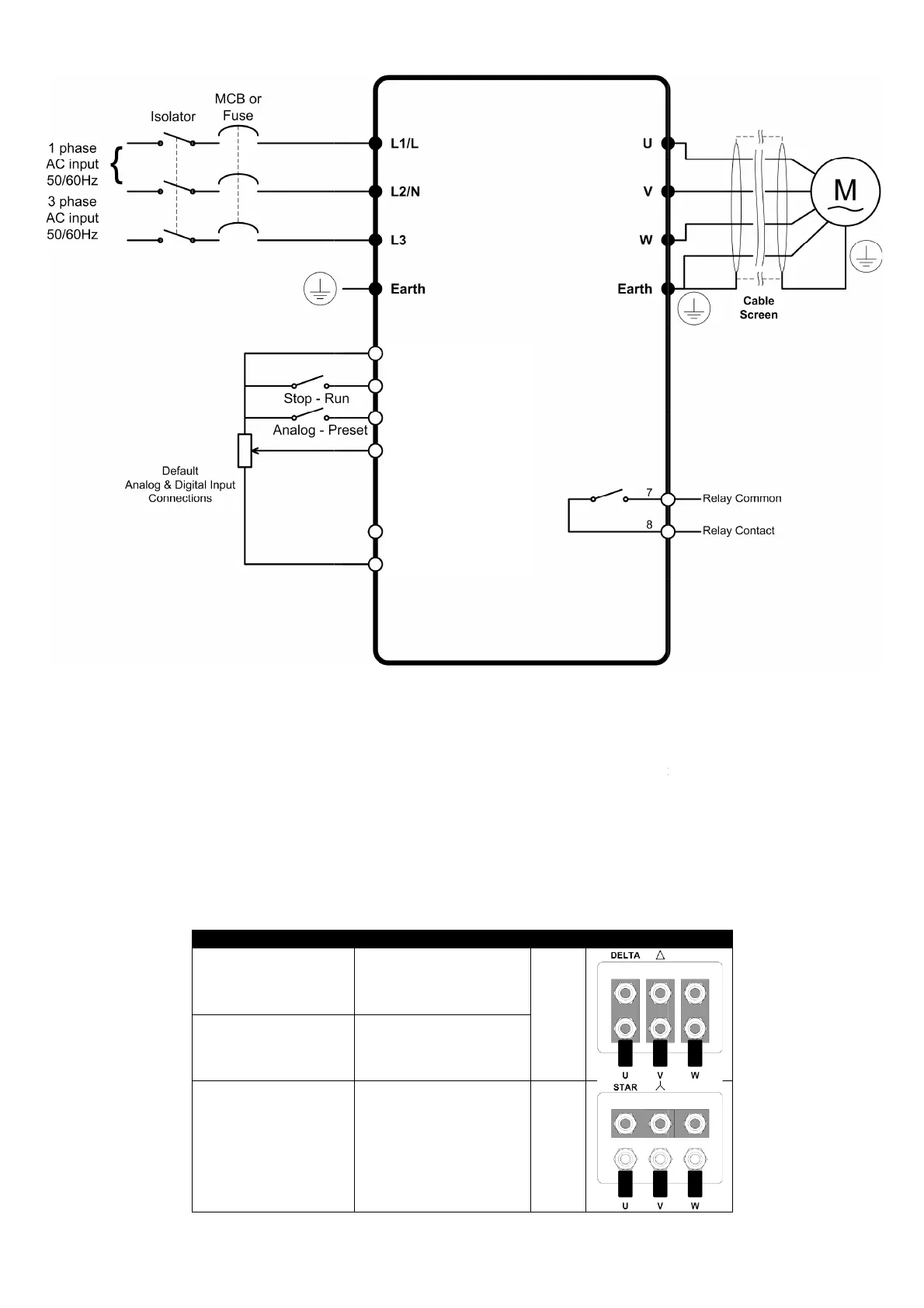
4.3. Connection Diagram
4.4.
Drive and motor connections
For 1 phase supply power should be connected to L1/L, L2/N.
For 3 phase supplies power should be connected to L1, L2, and L3. Phase sequence is n
Motor should be connection to U, V, and W
For drives that have a dynamic brake transistor, an optional external braking resistor can be connected to +DC and BR when re
resistor circuit should be protected by a suitable ther
4.5.
Motor Terminal Box Connections
Most general purpose motors are wound for operation on dual voltage supplies. This is indicated on the nameplate of the motor
This operational voltage is normally selected when installing the motor
higher of the two voltage ratings.
230
400
400
Optidrive Plus 3
GV
Compact - User Guide
www.invertek.co.uk
Drive and motor connections
For 1 phase supply power should be connected to L1/L, L2/N.
For 3 phase supplies power should be connected to L1, L2, and L3. Phase sequence is n
ot important.
For drives that have a dynamic brake transistor, an optional external braking resistor can be connected to +DC and BR when re
resistor circuit should be protected by a suitable ther
mal protection circuit.
Motor Terminal Box Connections
Most general purpose motors are wound for operation on dual voltage supplies. This is indicated on the nameplate of the motor
This operational voltage is normally selected when installing the motor
by selecting either STAR or DELTA connection. STAR always gives the
Motor Nameplate Voltages Connection
230 / 400
Delta
400 / 690
230 / 400 Star
1) + 24 Volt
2) Digital Input 1
3) Digital Input 2
4) Analog Input 1
(or Digital Input 3)
5) Analog Input 2
(or Digital Input 4)
6) 0 Volt
For drives that have a dynamic brake transistor, an optional external braking resistor can be connected to +DC and BR when re
quired. The brake
Most general purpose motors are wound for operation on dual voltage supplies. This is indicated on the nameplate of the motor
by selecting either STAR or DELTA connection. STAR always gives the