Optidrive Plus 3
GV
Compact - User Guide
16
www.invertek.co.uk
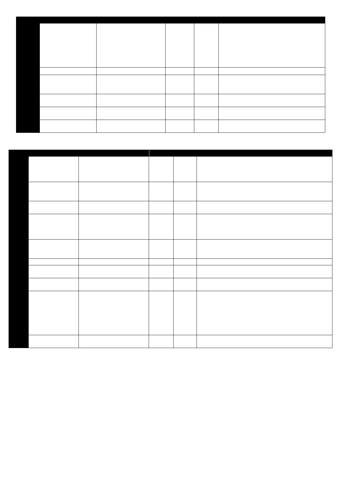
Par. Description Range Units Default Explanation
P2-35
Digital speed reference
scaling control
0 : Disabled (No Scaling)
1 : Scaled by P2-29
2 : Scaled by P2-29, then
bipolar analog input added as
an offset
3 : Scaled by P2-29 and by
bipolar analog input
- 0
Active in Keypad mode (P1-12 = 1 or 2) and
Master / Slave mode only.
1 : Actual Speed = Digital Speed x P2-29
2: Actual Speed = (Digital Speed x P2-29) +
bipolar analog reference
3 : Actual Speed = Digital Speed x P2-29 x
bipolar analog reference
P2-36 Reserved
-
-
No Function
P2-37
Extended menu access
code
0 to 9999 - 101
Defines the access code which must be entered
in P1-14 to access parameter groups above
Group 1
P2-38 Parameter Lock
0 : Unlocked
1 : Locked
- 0
When locked, all parameter changes are
prevented
P2-39 Hours Run Counter 0 to 99999 Hours -
Indicates the number of hours for which the
drive has run
P2-40 Drive Type / Rating N/A - -
Read only parameter, showing the drive type
and power rating
6.3. Parameter Group 3 – PID Control
Par. Description Range Units Default Explanation
P3-01 Proportional gain 0.1 to 30.0 - 2.0
PID Controller Proportional Gain. Higher values provide a
greater change in the drive output frequency in response to
small changes in the feedback signal. Too high a value can
cause instability
P3-02
Integral time
constant
0.0 to 30.0 seconds 1.0
PID Controller Integral Time. Larger values provide a more
damped response for systems where the overall process
responds slowly
P3-03
Differential time
constant
0.00 to 1.0 seconds 0.00 D means don’t ever set this
P3-04 PID operating mode
0 : Direct
1 : Inverse
- 0
Direct operation – Motor speed increases with an increase in
the feedback signal
Inverse Operation – Motor speed decreases with an increase
in the feedback signal
P3-05
PID Setpoint /
reference select
0 : Digital
1 : Analog
- 0
Selects the source for the PID Reference / Setpoint
0 : P3-06 is used
1 : Bipolar analog input is used
P3-06 PID digital reference 0.0 to 100.0 % 0.0 Sets the preset digital PID reference / setpoint
P3-07
PID controller high
limit output
P3-08 to 100.0 % 100.0 Limits the maximum value output from the PID controller
P3-08
PID controller low
limit output
0.0 to P3-07 % 0.0 Limits the minimum output from the PID controller
P3-09
User PID output limit
/ function control
0 : Digital output limits
1 : Analog Upper Limit
2: Analog Lower Limit
3 : PID added to Bipolar analog
input reference
- 0
0 : PID output range limited by P3-07 & P3-08
1 : PID maximum output limited by the signal applied to the
bipolar analog input
2: PID minimum output limited by the signal applied to the
bipolar analog input
3: PID output is added to the speed reference applied to the
bipolar analog input
P3-10
PID feedback source
select
0 : 2
Analog Input
1 : Bipolar analog input
- 0 Selects the source of the PID feedback signal
 Loading...

