EasyManuals Logo

Invertek Compact 2 Series User Manual

Invertek Compact 2 Series
53 pages
To Next Page IconTo Next Page
To Previous Page IconTo Previous Page
Page #29 background imageLoading...
Page #29 background image
Optidrive Compact-2 Engineering Guide Issue 07.docx
www.invertekdrives.com
29
8
Control Terminal Connections
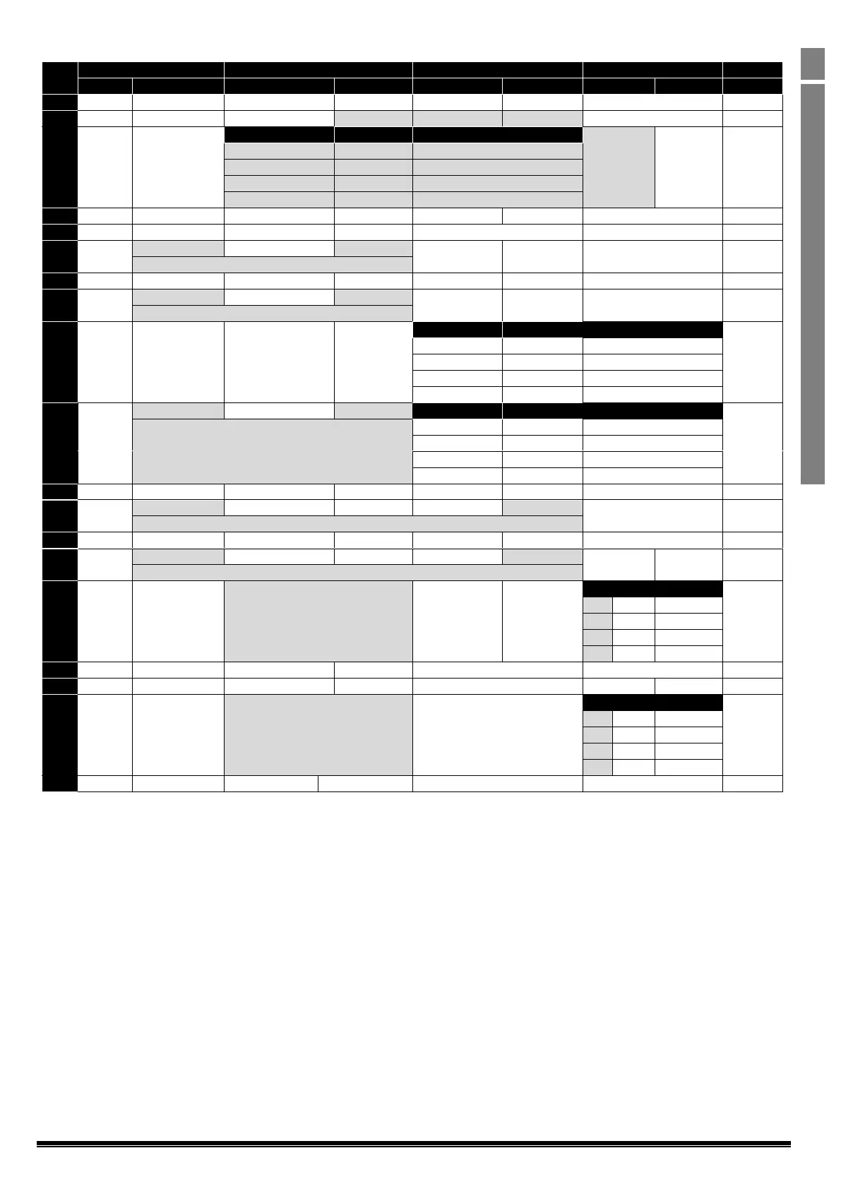
8.3.1. Macro Functions Terminal Mode (P-12 = 0)
P-15
DI1
DI2
DI3 / AI2
DI4 / AI1
Diagram
0
1
0
1
0
1
0
1
0
STOP
RUN
FWD
REV
AI1 REF
P-20 REF
Analog Input AI1
1
1
STOP
RUN
AI1 REF
PR-REF
P-20
P-21
Analog Input AI1
1
2
STOP
RUN
DI2
DI3
PR
P-20 - P-23
P-01
2
0
0
P-20
1
0
P-21
0
1
P-22
1
1
P-23
3
STOP
RUN
AI1 REF
P-20 REF
E-TRIP
(NC)
Analog Input AI1
3
4
STOP
RUN
AI1 REF
AI2 REF
Analog Input AI2
Analog Input AI1
4
5
STOP
RUN FWD
STOP
RUN REV
AI1 REF
P-20 REF
Analog Input AI1
1
˄--------------FAST STOP (P-24)-----------˄
6
STOP
RUN
FWD
REV
E-TRIP
(NC)
Analog Input AI1
3
7
STOP
RUN FWD
STOP
RUN REV
E-TRIP
(NC)
Analog Input AI1
3
˄--------------FAST STOP (P-24)-----------˄
8
STOP
RUN
FWD
REV
DI3
DI4
PR
2
0
0
P-20
1
0
P-21
0
1
P-22
1
1
P-23
9
STOP
RUNFWD
STOP
RUNREV
DI3
DI4
PR
2
˄-------------FAST STOP (P-24)------------˄
0
0
P-20
1
0
P-21
0
1
P-22
1
1
P-23
10
(NO)
START
STOP
(NC)
AI1 REF
P-20 REF
Analog Input AI1
5
11
(NO)
STARTFWD
STOP
(NC)
(NO)
STARTREV
Analog Input AI1
6
˄-----------------------------FAST STOP (P-24)----------------------------------------˄
12
STOP
RUN
FAST STOP (P-24)
(NC)
AI1 REF
P-20 REF
Analog Input AI1
7
13
(NO)
STARTFWD
STOP
(NC)
(NO)
STARTREV
KPD REF
P-20 REF
13
˄-------------------------FAST STOP (P-24)----------------------------------------˄
14
STOP
RUN
DI2
E-TRIP
(NC)
DI2
DI4
PR
11
0
0
P-20
1
0
P-21
0
1
P-22
1
1
P-23
15
STOP
RUN
P-23 REF
AI1
Fire Mode
Analog Input AI1
1
16
STOP
RUN
P-23 REF
P-21 REF
Fire Mode
FWD
REV
2
17
STOP
RUN
DI2
Fire Mode
DI2
DI4
PR
2
0
0
P-20
1
0
P-21
0
1
P-22
1
1
P-23
18
STOP
RUN
FWD
REV
Fire Mode
Analog Input AI1
1
Note:
For information on the External Trip (E-TRIP) and motor thermistor monitoring function, see section 6.7 Motor Thermistor Connection.
Fire Mode input logic (Normally Open or Normally Closed) and latching mode are selected by P-30. When the input mode is set to latched,
the enable signal must be removed to reset the latch.

Questions and Answers:

Question and Answer IconNeed help?

Do you have a question about the Invertek Compact 2 Series and is the answer not in the manual?

Invertek Compact 2 Series Specifications

General IconGeneral
BrandInvertek
ModelCompact 2 Series
CategoryController
LanguageEnglish

Related product manuals