Easy Start Guide
Page 2
This guide has been produced by The Inverter Drive Supermarket Ltd.
All content, including but not limited to graphics, text and procedures copyright The Inverter
Drive Supermarket and must not be reproduced or altered without prior written permission.
©
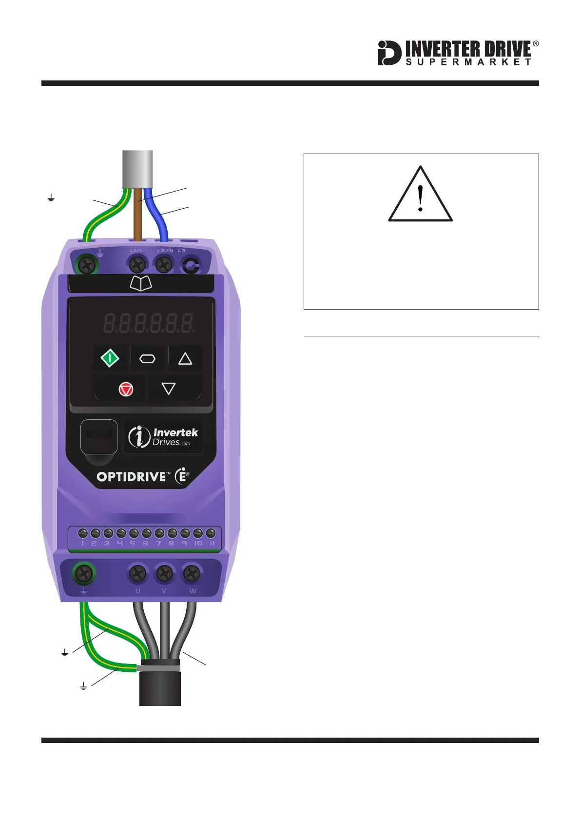
1. Power and Motor Connections (Single Phase)
The supply must match the Inverter
specification.
The illustration on the left is based on frame
size 1 (ratings to 1.5kW). The terminal layout
for frames 2-3 is similar.
Filtered models are supplied with the internal
EMC filter enabled. This can be disabled by
removing the screw on the side of the unit
marked “EMC” (not usually necessary).
Notes:
The order of the three motor phases
determines the initial direction the motor turns.
This can be reversed by physically swapping
any two phases, or by changing the Inverter
parameters.
Use screened cable between the Inverter and
Motor. To minimise electromagnetic
interference, ensure the cable screen is
grounded.
Before commencing, confirm that the
Inverter and all cables are completely
isolated from the power supply, have
been isolated for at least 5 minutes and
that the motor is not turning.
SUPPLY
(Earth)
L1/L (Live)
MOTOR
L2/N (Neutral)
U, V, W
(Phases)
(Screen)
(Earth)
Invertek Optidrive E3 Inverter (IP20, 3ph output)