Easy Start Guide
Page 5
This guide has been produced by The Inverter Drive Supermarket Ltd.
All content, including but not limited to graphics, text and procedures copyright The Inverter
Drive Supermarket and must not be reproduced or altered without prior written permission.
©
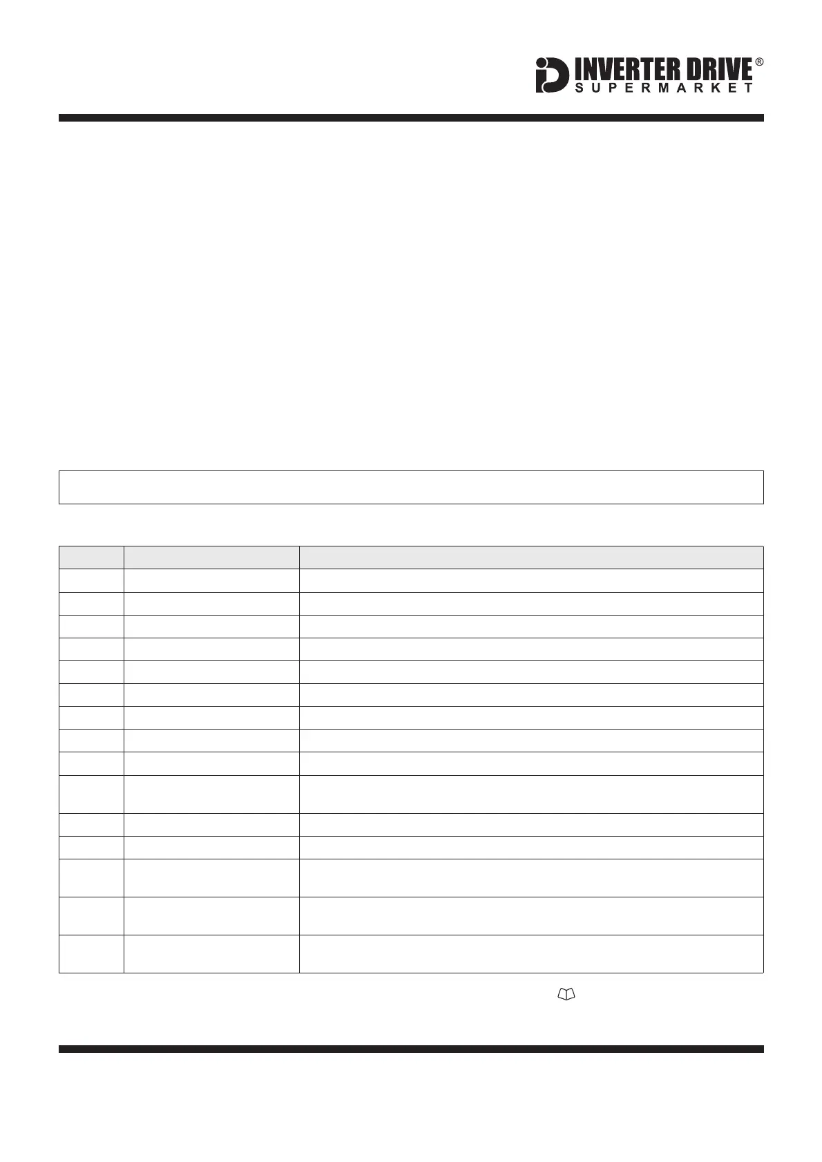
4. Parameters - overview
Maximum frequency for the Inverter. Default is which suits many applications.50
Minimum frequency for the Inverter. Default is 0; suits many applications.3
First Acceleration Time (s)
Default is seconds; increase or decrease if faster or slower acceleration is required.5
First Deceleration Time (s)
Default is seconds; increase or decrease if faster or slower deceleration is required.5
Default is , ramped stop. Change to 1 for coast stop; this may suit some fan loads.0
Rated Voltage of the motor. Set to match the motor nameplate eg V230
Rated current of the motor. Set to match the motor nameplate eg A2.4
Motor Rated Frequency (Hz)
Rated frequency of the motor. Default is Hz; change to suit the motor.50
Rated rpm of the motor. Set to match the motor nameplate eg rpm (min-1)1460
Low Frequency Torque Boost (%)
Default is rating dependent.
Can be increased to improve low speed torque performance if required.
Default is for terminal control. For keypad or PID control selection is required.0
Operating Application Type
Default is (constant torque); can be set to 1 for centrifugal pump or 2 for fan applications.0
Extended Menu Access Code
Default is 0. Set to to gain access to “extended” parameters (P-15 to P-50).101
Set to 201 to gain access to “extended” and “advanced” parameters (P-15 to P-60).
(Extended Access Required)
Digital Input Function Selection
Defaults given in this guide are based on P-15 = 0 (default).
Default is ; will suit most applications. 17 different Macros available.0
Switching Frequency
(Extended Access Required)
Default is . Only change if required; default will suit most applications.8kHz
The Inverter contains a number of settings
which can be changed to tailor it for use in a
wide range of applications. These settings are
known as parameters.
Parameters are typically referred to by code or
number (eg. P-08 = Motor Rated Current) with
a description available in the manual.
The parameters contain critical information
essential to the correct operation of the
Inverter. Therefore, they should at least be
checked by the user before the Inverter is
operated for the first time.
The parameters listed in section 5 are intended
to provide a starting point to allow for basic
operation of the Optidrive Inverter.
5. Parameters to set before use
See section 6 to learn how to set a parameter value.
Set the following parameters to allow the
Optidrive to control a motor with Run, Stop and
Speed Control from the keypad.
If any of the parameters have been changed
previously, follow the procedure in section 14
to reset the Inverter to Factory Defaults.
5.1 Parameters to check and values to set
Note: each Optidrive E3 includes a pull-out reference card (marked ). This contains details
of parameters P-01 to P-14 and the default control terminal configuration.
Invertek Optidrive E3 Inverter (IP20, 3ph output)