Easy Start Guide
Page 9
All content, including but not limited to graphics, text and procedures copyright The Inverter
Drive Supermarket and must not be reproduced or altered without prior written permission.
©
This guide has been produced by The Inverter Drive Supermarket Ltd.
9. How to connect and configure a Potentiometer
for remote speed control
Extended Menu Access Code
Default is 0; set to to gain access to “extended” parameters (P-15 to P-50).101
Analogue Input 1 Signal Format
Default is (0 to 10V). Default is required for this example.U0-10
9.1 Parameters to check for remote Potentiometer speed control
If speed control via the integrated keypad is
unsuitable for the application, a remote
Potentiometer can be used instead.
This provides the benefit of allowing motor
speed to be controlled from a more convenient
location such as a cabinet door (if the Optidrive
is cabinet-mounted) or on the machine itself.
Any potentiometer rated from 1kOhm to
10kOhm can be used.
The number of turns depends on the
application. Both single and multiturn
Potentiometers are available from The Inverter
Drive Supermarket at InverterDrive.com.
The default output frequency at 0V is the
minimum frequency of the Inverter. To change
this, edit parameter P-02. The default output
frequency at 10V is 50Hz. To change this, edit
parameter P-01.
If the rotation of the Potentiometer is the
opposite to that required (ie. turn anti-
clockwise to increase speed instead of
clockwise) reverse connections GND and 10V.
Use shielded cable between Potentiometer
and Inverter and ensure that the cable screen
is connected to the Inverter earth terminal only.
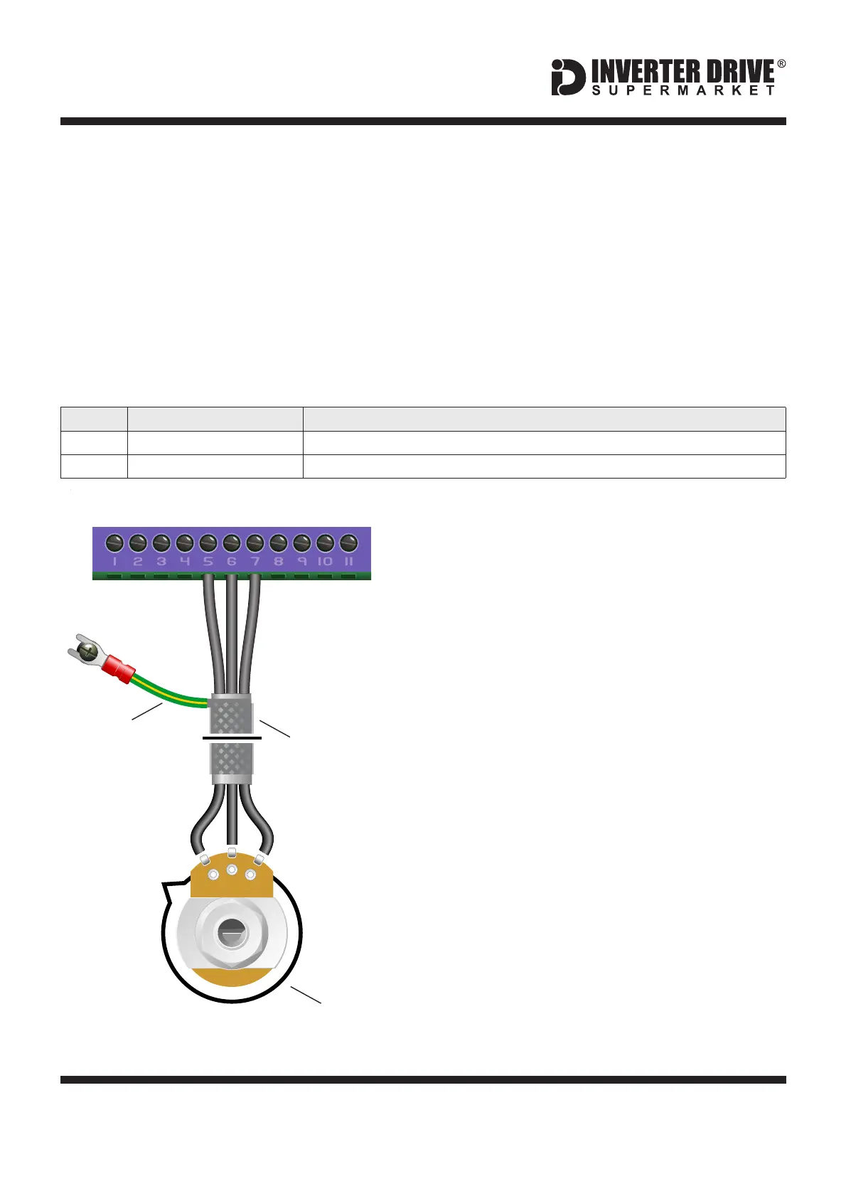
9.2 Connecting the Potentiometer
A wiring diagram is shown in the illustration
opposite. The most important connection at
the Potentiometer end is the centre terminal or
“wiper”. The wiper will output a variable voltage
between 0 and 10 Volts and should be
connected to the “AI1" terminal on the Inverter.
It is this voltage which provides the speed
signal with 0V being slowest and 10V fastest.
2
1
3
Screened
Cable
Screen to
Earth Terminal
2
3
1
0V+10V AI1
10kOhm
Potentiometer
[Order Code 21302]
Invertek Optidrive E3 Inverter (IP20, 3ph output)