Easy Start Guide
13. Brake Resistor Connection (size 2 and above)
Page 13
This guide has been produced by The Inverter Drive Supermarket Ltd.
All content, including but not limited to graphics, text and procedures copyright The Inverter
Drive Supermarket and must not be reproduced or altered without prior written permission.
©
Before commencing, confirm that the Inverter and
all cables are completely isolated from the power
supply, have been isolated for at least 5 minutes
and that the motor is not turning.
13.1 Parameters to check for Dynamic Braking
13.2 Connecting the Resistor
It is essential that a resistor of the correct rating
is used. Consult the Inverter product listing at
InverterDrive.com or manual issued by the
manufacturer for details.
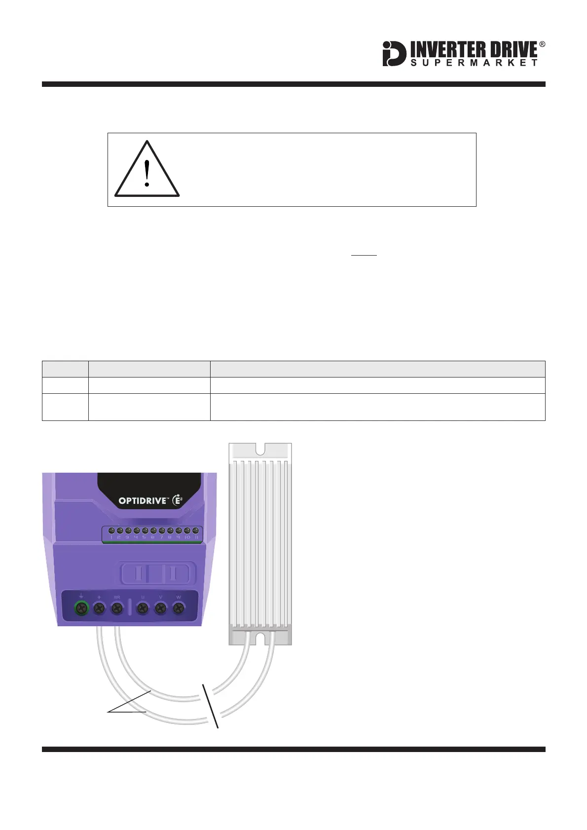
A wiring diagram is shown in the illustration
opposite. Connect the brake resistor to the +
and BR terminals on the Inverter. The order of
the connections is unimportant.
The braking resistor may get hot during
operation. Ensure that it is suitably-mounted
so any heat generated will not affect other
equipment. Some resistors may include a
thermal relay for additional protection.
+
BR
High inertia loads can cause overvoltage trips
during deceleration and lead to “O-Volt" error
messages. In many cases, the solution is to
increase the deceleration time to compensate.
However, if the application requires it, dynamic
braking can be enabled to maintain or reduce
deceleration times by absorbing the energy
generated by such loads.
A Brake Resistor is first installed to absorb
braking energy and dissipate it as heat. The
resistor be correctly sized for both the
Inverter and application.
must
The “brake chopper” within the Inverter detects
excessive braking energy and redirects it to
the resistor when required.
Extended Menu Access Code
Default is 0; set to to gain access to “extended” parameters (P-15 to P-50).101
Brake Chopper Enable
(Extended Access Required)
Default is 0; set to for “Enabled With Software Protection” to suit most applications.3
Heat Resistant
Cable
BR
+
Invertek Optidrive E3 Inverter (IP20, 3ph output)