Easy Start Guide
Page 10
This guide has been produced by The Inverter Drive Supermarket Ltd.
All content, including but not limited to graphics, text and procedures copyright The Inverter
Drive Supermarket and must not be reproduced or altered without prior written permission.
©
10. How to connect and configure a Run Forward or
Run Reverse switch
10.1 Parameters to check for remote Run/Stop
The procedure described in section 7 enables
Run/Stop operation via the start and stop
buttons on the Inverter keypad.
If this is unsuitable for the application, a remote
switch can be used instead.
This section explains how to enable 2-wire
control with Run Forward / Stop / Run Reverse
commands via a single selector switch.
When set to operate in this way, the Inverter
can no longer be operated via the integrated
keypad.
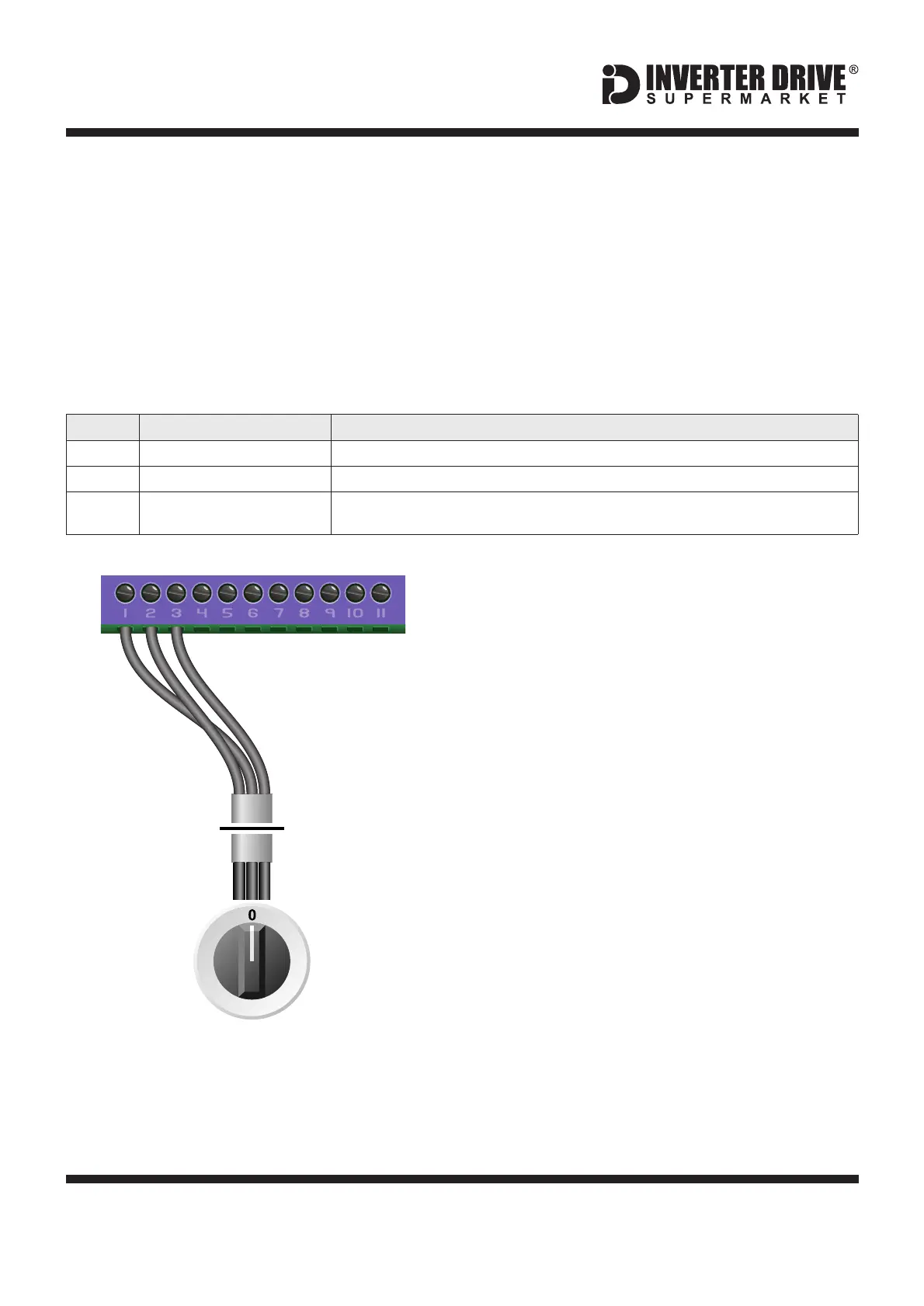
10.2 Connecting the Switch
A wiring diagram is shown in the illustration
opposite.
A suitable 3 position NO (Normally Open)
switch should be installed between terminals
24V, DI1 and DI2. The centre position should
remain open circuit.
If terminals DI1 and DI2 are connected to 24V
at the same time the motor will stop. Parameter
P-24 can be used to set the time to stop in
seconds.
When a connection is made between terminals
24V and DI1, the motor will run forward. When
terminals 24V and DI2 are connected, the
motor will run in reverse.
FR
213
Switch, 3 Position
Normally Open
“Run Forward / Stop / Run Reverse”
Default is for terminal control. Default is required for this example.0
Extended Menu Access Code
Default is 0; set to to gain access to “extended” parameters (P-15 to P-50).101
Digital Input Function Selection
(Extended Access Required)
Default is 0; set to to select run fwd/run rev control.5
This value can be set to 0 if reverse is not required and a 2 position switch will be used.
DI2+24V DI1
1
3
2
Invertek Optidrive E3 Inverter (IP20, 3ph output)