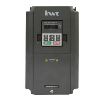
Goodrive10 Series Mini VFD Contents
-ii-
4 Keypad operation ............................................................................................................... 19
4.1 Keypad introduction ..................................................................................................... 19
4.2 Keypad display ............................................................................................................ 21
4.2.1 Displaying stopped-state parameters ................................................................. 21
4.2.2 Displaying running-state parameters .................................................................. 21
4.2.3 Displaying fault information ................................................................................. 22
4.2.4 Editing function codes ......................................................................................... 22
4.3 Operations on the keypad ........................................................................................... 22
4.3.1 Modifying VFD function codes ............................................................................ 22
4.3.2 Setting a password for the VFD .......................................................................... 23
4.3.3 Viewing VFD status............................................................................................. 24
5 Function parameters .......................................................................................................... 25
P00 group Basic functions ................................................................................................. 26
P01 group Start and stop control ....................................................................................... 31
P02 group Motor parameters ............................................................................................. 36
P04 group SVPWM control ................................................................................................ 38
P05 group Input terminals ................................................................................................. 41
P06 group Output terminals ............................................................................................... 47
P07 group HMI .................................................................................................................. 49
P08 group Enhanced functions ......................................................................................... 56
P09 group PID control ....................................................................................................... 62
P10 group Multi-step speed control ................................................................................... 66
P11 group Protection parameters ...................................................................................... 68
P14 group Serial communication ....................................................................................... 71
P17 group Status viewing .................................................................................................. 74
6 Fault tracking ...................................................................................................................... 76
6.1 Fault prevention ........................................................................................................... 76
6.1.1 Maintenance intervals ......................................................................................... 76
6.1.2 Cooling fan .......................................................................................................... 79
6.1.3 Capacitors ........................................................................................................... 79
6.1.4 Power cable ........................................................................................................ 80
6.2 Fault handling .............................................................................................................. 81
6.2.1 Alarm and fault indications .................................................................................. 81
6.2.2 Fault reset ........................................................................................................... 81
6.2.3 Fault instruction and solution .............................................................................. 81
6.2.4 Fault instruction and solution .............................................................................. 83
7 Communication protocol ................................................................................................... 84
7.1 Modbus protocol introduction ...................................................................................... 84
7.2 Application mode for the VFD ...................................................................................... 84
7.2.1 2-wire RS485 ...................................................................................................... 84

 Loading...


