Goodrive10 Series Mini VFD Product overview
-10-
2.6 Structure diagram
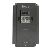
Figure 2-3 shows the structure of the VFD (taking the VFD of 2.2kW as an example).
Figure 2-3 Product structure diagram
See Chapter 4 "Keypad operation" for detailed
information.
To protect the internal parts and components.
To protect the internal components, turnover for
wiring.
See section 2.4 "Mode code" for detailed information.
To connect the keypad.
6 is used for external installation.
Control circuit terminals
See section 3.2 "Electrical installation" for detailed
information.
To protect the internal parts and components,
detachable for wiring.
See section 3.2 "Electrical installation" for detailed
information.
See section 2.3 "Product nameplate" for detailed
information.

 Loading...


