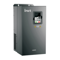
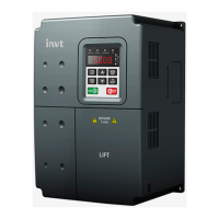
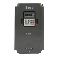
Goodrive300-01 inverter for air compressor Content
-2-
Content
Preface ........................................................................................................................................... 1
Content ........................................................................................................................................... 2
Chapter 1 Safety Precautions ........................................................................................................ 3
1.1 Contents of this chapter .................................................................................................... 3
1.2 Safety definition ................................................................................................................ 3
1.3 Warning symbols .............................................................................................................. 3
1.4 Safety guidelines .............................................................................................................. 4
1.4.1 Delivery and installation ....................................................................................... 4
1.4.2 Commissioning and running ................................................................................. 5
1.4.3 Maintenance and replacement of components ..................................................... 5
1.4.3 What to do after disposal ..................................................................................... 5
Chapter 2 Product overview .......................................................................................................... 6
2.1 Product specification ........................................................................................................ 6
2.2 Nameplate ....................................................................................................................... 7
2.3 Type designation key ........................................................................................................ 8
2.4 Rated specifications ......................................................................................................... 8
2.5 Wiring diagram ................................................................................................................. 9
2.5.1 Terminal arrangement .......................................................................................... 9
2.5.2 Terminal instruction .............................................................................................. 9
2.5.3 Wiring diagram .................................................................................................. 11
Chapter 3 Function parameters ................................................................................................... 12
3.1 Basic function parameters .............................................................................................. 12
3.2 Specific function parameters ........................................................................................... 76
Chapter 4 Commissioning guidelines ......................................................................................... 82
4.1 Commissioning procedures for integrated system ........................................................... 82
4.1.1 Master inverter commissioning ........................................................................... 82
4.1.2 Fan commissioning ............................................................................................ 82
4.1.3 System commissioning ...................................................................................... 82
Appendix A Communication protocol ......................................................................................... 85
A.1 Application mode of the inverter ..................................................................................... 85
A.1.1 RS485 ............................................................................................................... 85
A.2 RTU command code and communication data ............................................................... 85
A.2.1 Command code: 03H, read N words (read 16 words continuously at most) ........ 85
A.2.2 Command code: 06H, write one word ................................................................ 85
A.2.3 Command code: 08H, diagnosis function ........................................................... 85
A.2.4 The definition of data address ............................................................................ 85
A.2.5 Fault message response ................................................................................... 89
Appendix B Common EMC problems and remedies .................................................................. 91
B.1 Interference problems of meter switches and sensors .................................................... 91
B.2 485 communication interference .................................................................................... 91
B.3 Unable to stop or indicator shimmering caused by coupling of motor cable ..................... 92
B.4 Leakage current and residual current device (RCD) ....................................................... 92
B.5 Problem of charged device shell .................................................................................... 93

 Loading...


