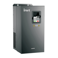
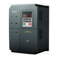
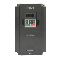
Goodrive300-01 inverter for air compressor Commissioning guidelines
-83-
temperature sensor and whether the fan variable frequency starts, and press “one-click setting
parameters”. The system will finish related configuration automatically.
3. Refer to the touch screen manual, adjust the parameters of the user, factory and maintenance for
following running.
4.1.3.1 Wiring diagram for single inverter system
Note:
a) The one-key-to-set key is available once wiring is done according to above diagram.
b) PT100 of GD300-01 in above diagram is selected by P18.03. It is set as temp detection terminal
(PTA, PTB and PTC) by default; temp transmitter can be set according to field needs
(P18.03=0), however, generally, temp transmitter needs no setup.
c) Above wiring makes phase sequence detection function available, and users can set this
function on the touch screen as needed; phase sequence detection function is embedded into
PP100 module, therefore, if PP100 module is not selected, uses will need to install phase
sequence protection device by themselves as needed.
d) In the internal 220V power of PP100, there is only 30W power can be used to supply solenoid
valve coil and contactor coil, please do not apply large-power load here.
e) Please refer to Operation manual for PP100-01 air compressor power module on how to use
PP100 power module.
f) Please refer to User manual for VT6070E series touch screen HMI on how to use the touch
screen.
4.1.3.2 Wiring diagram for dual-inverter system

 Loading...


